Gage Bilt GB2600A Original Instructions Manual - Page 7
Browse online or download pdf Original Instructions Manual for Power Tool Gage Bilt GB2600A. Gage Bilt GB2600A 16 pages. Installation tool
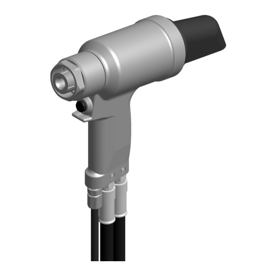
When the tool is connected to a power unit, operation is controlled by an electric actuator (GB2600) or a piloted air actuator (GB2600A) in
the handle. When the actuator is depressed, a directional valve in the power unit directs oil to the front side of the piston forcing it
and the nose assembly collet rearward. This action causes the jaws to clamp onto the fastener pintail and pull the sheets together. The
anvil is forced forward, swaging the collar into locking grooves of the fastener. Further force breaks the pintail off, approximately flush
with the collar.
When the actuator is released the directional valve reverses oil flow to the back of the piston and pushes the nose assembly off of the
swaged fastener. The pintail is ejected out of the rear of the handle assy.
PULL Cycle
Actuator
PULL Pressure
GB2600 / GB2600A INTALLATION TOOL S/N: 1001 AND ABOVE
PLEASE CONTACT GAGE BILT FOR ALL OTHER SERIAL NUMBERS
PRINCIPLE OF OPERATION
HYDRAULIC DIAGRAM
Relief
Valve
RETURN Pressure
Images may not reflect actual tool
Actuator
PULL Pressure
Pressurized Oil
Unpressurized Oil
7
RETURN Cycle
Relief
Valve
RETURN Pressure
REV 1/20