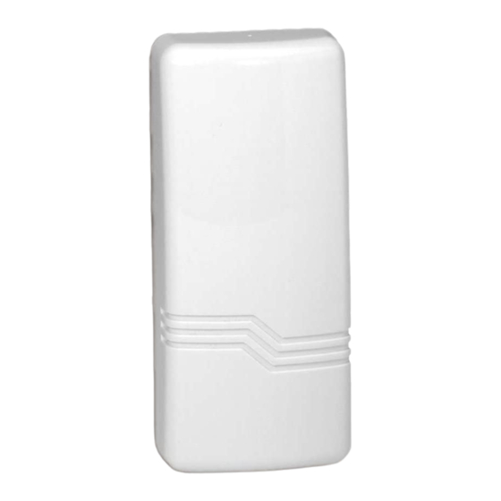
ADEMCO 5817CB Installation Instructions - Page 3
Browse online or download pdf Installation Instructions for Transmitter ADEMCO 5817CB. ADEMCO 5817CB 4 pages. Wireless commercial /
household transmitter
Also for ADEMCO 5817CB: Quick Start Manual (2 pages), Installation And Setup Manual (2 pages), Installation Instructions (2 pages), Installation And Setup Manual (2 pages)

Note : Replace battery only with: Duracell DL123A, Sanyo CR123A,
Panasonic CR123A, Ademco 466, Varta CR123A, or Tekcell CR123A.
CAUTION:
3.
To replace the cover, engage the hooks along the top edge and snap shut.
SPECIFICATIONS
Dimensions
1-9/16"W x 3-1/2"H x 1-3/16"D (40mm x 89mm x 30mm)
Battery 3V Lithium (see BATTERY INSTALLATION/REPLACEMENT).
UL Listings:
Commercial Fire....................................... UL864
Household Fire......................................... UL985
Household Burg ....................................... UL1023
Commercial Burg ..................................... UL365, UL609, UL1076, UL1610
TO THE INSTALLER
Regular maintenance and inspection (at least annually) by the installer and frequent testing
by the user are vital to continuous satisfactory operation of any alarm system.
The installer should assume the responsibility of developing and offering a regular
maintenance program to the user, as well as acquainting the user with the proper operation
and limitations of the alarm system and its component parts. Recommendations must be
included for a specific program of frequent testing (at least weekly) to insure the system's
operation at all times.
FOR DETAILS ON LIMITATIONS OF THE ENTIRE ALARM SYSTEM, REFER TO THE
CONTROL PANEL'S INSTALLATION INSTRUCTIONS FOR THE RECEIVER/CONTROL WITH
WHICH THIS DEVICE IS USED.
NOTE:
For UL commercial and household fire
installations, only one initiating device may be
connected to this transmitter. For UL commercial
burglary installations, multiple initiating devices
may be used as long as the devices all service
the same function such as door/window contacts,
motion or glassbreak detectors. All initiating
devices must be located within the same room.
THE DIP SWITCHES MUST BE
SET AS SHOWN DURING
ENROLLMENT BY THE CONTROL
DIP SWITCH FOR PRIMARY LOOP OPTIONS
SHOWN SET FOR: 1. SINGLE TRANSMISSION
Risk of fire, explosion, and burns. Do not recharge, disassemble,
heat above 212°F (100°C), or incinerate. Dispose of used batteries
promptly. Keep away from children.
ON
ON
OFF
1
2
3
(SEE SETTINGS TABLE)
NOTE: SW2 MUST BE ON
SW3 MUST BE ON
SW4 MUST BE OFF
WIRING ACCESS
Diagram 2. Transmitter, Cover Removed
COVER
HOLDING
SLOTS (2)
WHITE AREA
INDICATES
SWITCH HANDLE
DIP
SWITCH
4
+
BATTERY
–
COVER
TAMPER
SWITCH
LOOP 3
TERMINALS
(AUX)
SLOT FOR
CONCEALED
N.C.
CONTACT
DEVICE
- 3 -
MOUNTING
PLATE
HOLE
TAMPER SWITCH
HOLD DOWN
CONCEALED
WIRING
ENTRY
HOLE
Diagram 1. Mounting Plate
ANTENNA
ALIGN MAGNET
WITH MARKS ON
CASE (2 PLACES)
LOOP 2
REED SWITCH
(AUX)
MAGNET
(OBTAIN
SEPARATELY)
1/2"
MAX.
PRIMARY
MOUNTING
LOOP 1
PLATE
TERMINALS
COVER
RELEASE
PRY-OFF
POINT
N.O.
CONTACT
470K ohms
EOLR
DEVICE
5817CB-002-V1
CASE
HOLDING
POSTS
MOUNTING
PLATE HOLES
LOCKING
TAB
5817CB-001-V0
