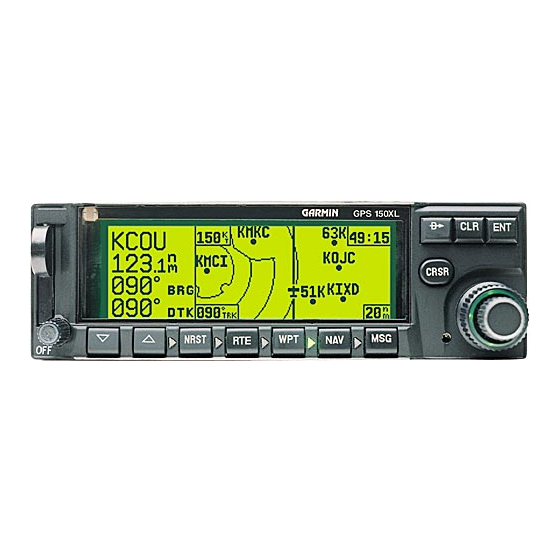
Garmin GNC 250 Maintenance And Repair Manual - Page 17
Browse online or download pdf Maintenance And Repair Manual for Avionics Display Garmin GNC 250. Garmin GNC 250 20 pages. Garmin gnc 250: quick reference
Also for Garmin GNC 250: Pilot’s Quick Reference Manual (25 pages), Installation Manual (44 pages)

2.4
TROUBLESHOOTING CHART
Unit will not power on
Unit will not power off
Display has horizontal
or vertical lines
Display has missing or
dark pixels
Display brightness not
adjustable manually
Display brightness not
adjustable via photocell
Keycaps have no
backlighting
Keycap backlighting not
uniform
Bezel Annunciators do
not function
No external annunciator
output(s) (message,
arrival, approach)
Keycaps do not function
properly
Dual concentric (rotary)
knobs do not function
properly
Approach arm switch not
functioning properly
(300 only)
Sequence Hold low
switch not functioning
properly (300 Only)
GPS reception weak or
GPS Status Page shows
low signal levels
MESSAGE
Check External Power Connection
Check Remote External Battery Pack (if equipped)
Check Pwr/Volume Switch Connection
Replace Pwr/Volume Switch (see Section 3.2.7)
Replace CPU Board (see Section 3.2.4)
Replace CPU Board (see Section 3.2.4)
Replace Pwr/Volume Switch (see Section 3.2.6)
Replace Display Board (see Section 3.2.8)
Replace CPU Board (see Section 3.2.4)
Replace Display Board (see Section 3.2.8)
Replace CPU Board (see Section 3.2.4)
Replace Control/Display Unit (see Section 3.2.1)
Replace Control/Display Unit (see Section 3.2.1)
Replace CPU Board (see Section 3.2.4)
Replace Control/Display Unit (see Section 3.2.1)
Replace CPU Board (see Section 3.2.4)
Replace Control/Display Unit (see Section 3.2.1)
Replace Display/Control Unit (see Section 3.2.1)
Replace CPU Board (see Section 3.2.4)
Check connections and verify operation in Test Mode
(see Section 4.2.3)
Replace CPU Board (see Section 3.2.4)
Replace Control/Display Unit (see Section 3.2.1)
Replace CPU Board (see Section 3.2.4)
Check Flex Circuit connection from rotary switch to
back of Control/Display Unit
Replace Rotary Switch Assembly (see Section 3.2.7)
Replace Display Board (see Section 3.2.8)
Replace CPU Board (see Section 3.2.4)
Check connections and verify operation in Test Mode
(see Section 4.2.3)
Replace external switch
Replace CPU Board (see Section 3.2.4)
Check connections and verify operation in Test Mode
(See Section 4.2.3)
Replace external switch
Replace Comm Chassis Sub Assy (see Section 3.2.2,
steps 1-7)
Replace CPU Board (see Section 3.2.4)
Replace Antenna and/or antenna cable
Replace GPS Receiver Board (see Section 3.2.5)
RECOMMENDED REPAIR
14
