Aqua Source Synergy 35 Installation Manual - Page 7
Browse online or download pdf Installation Manual for Water Filtration Systems Aqua Source Synergy 35. Aqua Source Synergy 35 18 pages. Drum filters
Please be aware of the following, with regard to a
maximum flow per pipe:
The pond water level should not fall too much. If the pond
water level falls by 1 cm, the flow per pipe may fall by as
much as 1 to 2 m3/hour. In case of large fluctuations of
the pond water level (due to evaporation, replenishing or if
you rinse the filter) there is a risk of insufficient water
being supplied to the filter. If your pump pumps more
water than flows into the filter, the drum will be pumped
empty and the sensor will appear above the water level,
which will cause the filter to go in rinse cycle.
If the supply pipes are of significant length, with many
bends, there will be lots of friction loss and a lot less than
10 m3/hour may be supplied per pipe.
Inlets/ Outlets that are not used should be
sealed.
Discharge of waste:
The waste will be sprayed by the nozzles onto the screen,
into the waste channel. The waste channel can be
connected directly to the sewer or to a drainage point.
Return to pond:
The pump is connected to the 110 mm outlet. If
necessary, make use of a flexible coupling, for a good
transit to your pump. A flexible connection will also reduce
vibrations.
Make sure that you never install a pump larger than
recommended for the filter. As you go towards the
maximum of the filter in terms of the selected pump, you
should ensure that sufficient water is supplied and that the
dry running function of the electronics is engaged. This is
indicated on the display Siemens Logo in the Electronics
Cabinet.
7.2.1 Setting for sensor/float
Upon delivery, the sensor has already been installed for
use as gravity and in such a way that it will function
properly in most situations. You may need to check for
correct functioning after installation and adjust the float
accordingly.
3: Normal position (recommended)
4: Lowest position
If the float is in lowest position (4), the filter will postpone
the rinsing function, creating more pressure in the drum
(not recommended), although in case of too little water
supply from the bottom drains, this could be a temporary
solution, so the filter can keep running. If the float is in
highest position (image 5) the filter will rinse more quickly
and more often. Image 3 represents the
'normal' position, recommended for most ponds.
The cables of the float must be connected to numbers 1
and 2 in the electronics box. The wires of the magnet
contact must be connected to numbers 3 and 4.
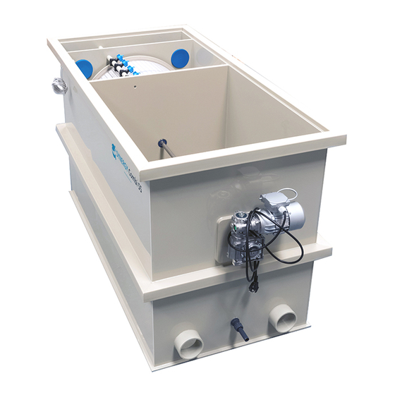
7.2.3. Connecting the rinse pump
The Rinse pump is included with the Synergy drum filters
and Synergy Combi, as standard. (Oase Garden Pro 3000)
For fitting, you can use one of the 110 mm exits, by
applying an adapter (ring) size 32 or 25 mm for the rinse
pump. Or position yourself at a location of your choice,
using a 1" tank connector. Make sure that you assemble
this connector into the 'clean' side of the filter and not into
the first chamber where the dirt enters. This is to prevent
clogging of the spray nozzles.
The flushing pump (included) must be installed later with a
coupling (included) to the threaded pipe protruding from the
DRUM chamber. We recommend also using a header tank
connected to an outside source, such as a garden tap to enable
the pump to use clean water sprayed onto the DRUM Screen
The Pump takes 1" male threaded BSP fittings reduced down to
¾" (supplied) to feed the Spray Bar
All you need is ¾" Pressure pipe to finish the connection.
The feed pipe to the pump can be done with 1" pipe either
from the Drum or from a freshwater header tank.
NB;Fittings/pipe will be needed to suit your own preference for
the water feed to the pump and spray bar. ( 1" and ¾" pipe).
Fitting kit included to join Pump to Spray bar, (All other
Connections/Pipe not included)
5: Highest position
6:tank
connector