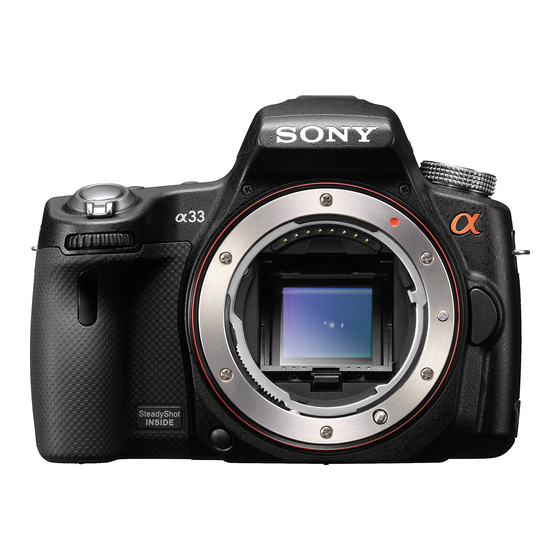
Sony SLT-A55V - alpha; Translucent Mirror Technology™ Dslr Service Manual - Page 28
Browse online or download pdf Service Manual for Digital Camera Sony SLT-A55V - alpha; Translucent Mirror Technology™ Dslr. Sony SLT-A55V - alpha; Translucent Mirror Technology™ Dslr 30 pages. Interchangeable lens digital camera/zoom lens kit
Also for Sony SLT-A55V - alpha; Translucent Mirror Technology™ Dslr: Function Manual (7 pages), Specifications (2 pages)

Assembly-8: Mirror Box Sub Unit
1-1. AF Driving Unit
#164: M2.0 X 3.9
(Black)
3-268-954-11
2.0
3.9
Screw
AF Driving Unit
1-2. EM A Mount Lug Plate (Lower)
Boss
Claw
EM A Mount Lug Plate (Lower)
SLT-A33/A33L/A33Y/A55/A55V/A55L/A55VL/A55VY_L2
1-3. AP Aperture Unit Charge Position Setting
1� Check that the AP Aperture Unit is in a free state.
�
∗ Refer to "1-5. AP Aperture Unit Free Position Setting" for
the setting and the confirming method at the free position.
2� Set the Iris Joint Gear by aligning the A portion of
�
AP Aperture Unit with the B portion (U groove) of
Iris Joint Gear.
AP Aperture Unit
A
B
Iris Joint Gear
3� After setting, rotate the Iris Joint Gear by
180°
to
210°
the position shown with the arrow mark.
1-4.
AP Aperture Unit
∗ Attach the Iris Joint Gear to the AP Aperture Unit, and then attach
them to the MB Front Frame Assy with the AP Aperture Unit being on
charge position.
∗ Refer to "1-3. AP Aperture Unit Charge Position Setting" for
the confirm method at the charge position.
#64: M1.7 X 5.0 (Tapping)
(Silver)
2-666-551-21
MB Front Frame Assy
in
Boss
Soldering
1-5. AP Aperture Unit Free Position Setting
The AP Aperture Unit returns to the original potion when the Iris Joint
Gear is removed from it.
3-3
1-6. Ring Roller (A) (SV), Iris Ring
1� Attach the Ring Roller (A) (SV) to the MB Front Frame Assy.
�
∗ When attaching the Ring Roller (A) (SV), be sure to
remove the Iris Ring beforehand.
2 Attach the Iris Ring by aligning it with the stop position
�
(iris-in end) of drawing.
Screw
1.7
5.0
1-7. Ring Roller (B) (SV), AP Ring Roller C, Ring Roller Shaft (C) (SV)
Ring Roller (B) (SV)
Ring Roller (B) (SV)
Iris Ring
AP Ring Roller C
Ring Roller Shaft (C) (SV)
AP Ring Roller C
AP Aperture Unit
G G-85
Ring Roller Shaft (C) (SV)
AP Ring Roller C
Iris Ring
Ring Roller Shaft (C) (SV)
Ring Roller (A) (SV)
Ring Roller (A) (SV)
Iris Ring
Stop Position (iris-in end)
