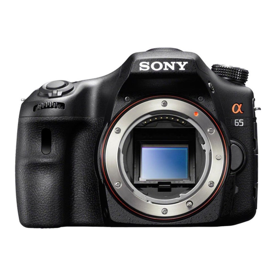
Sony SLT-A65V &alpha Service Manual - Page 34
Browse online or download pdf Service Manual for Digital Camera Sony SLT-A65V &alpha. Sony SLT-A65V &alpha 36 pages. Interchangeable-lens digital camera with built-in flash
Also for Sony SLT-A65V &alpha: Brochure & Specs (10 pages), Specifications (35 pages), Limited Warranty (1 pages), Correction (2 pages), Specifications (2 pages), Function Manual (3 pages)

Ver. 1.5 2012.11
The changed portions from
Ver. 1.4 are shown in blue.
Assembly-1: Routing of the Flash Harness.
Flash Harnesses
Ribs
Tape
Connector
Assembly-2: Assemble ALX-8630 (AF Module)
A Tighten the S Adjustment
Screws
completely.
B Loosen the S Adjustment
Screws evenly by 1.5 turns.
Assembly-3: Assemble Shutter Unit (AFE-3032)
When install Shutter Unit (AFE-3032), check MB Shutter Charge
Lever is downward.
MB Shutter
Charge Lever
SLT-A65/A65K/A65L/A65M/A65V/A65VK/A65VL/A65VM/A65VX/A65VY/A65X/A65Y_L2
Assembly-4: Mirror Box Sub Unit
4-1. Ring Roller (A) (SV), AP Iris Ring
A Attach the Ring Roller (A) (SV) to the MB Front Frame Assy.
When attaching the Ring Roller (A) (SV), be sure to
remove the AP Iris Ring beforehand.
B Attach the AP Iris Ring by aligning it with the stop position
(iris-in end) of drawing.
Ring Roller (A) (SV)
Ring Roller (A) (SV)
AP Iris Ring
Stop Position (iris-in end)
4-2. Ring Roller (B) (SV), AP Ring Roller C,
Ring Roller Shaft (C) (SV)
Ring Roller (B) (SV)
Ring Roller (B) (SV)
AP Iris Ring
AP Ring Roller C
Ring Roller Shaft (C) (SV)
AP Ring Roller C
GG-85
Ring Roller Shaft (C) (SV)
AP Ring Roller C
AP Iris Ring
Shutter Unit
Ring Roller Shaft (C) (SV)
(AFE-3032)
3. ASSEMBLY
4-3. MB Ring SP COM, MB Mount Spacer, H Mount
MB Ring SP COM
GG-85
MB Mount Spacer
MB H Mount
5
2
4
1
3-1
4-4. AP Sensor Gear Setting Position.
AP Sensor Gear
4-5. Gears Setting Position.
3
MB Shutter
Charge SP
6
MB Shutter Charge
Camgear Assy
MB Deceleration
Gear 2
AP Sensor Gear
Hole
MB Shutter
Charge Lever
MB Lever
Cushion
MB Deceleration
Gear 1
