Yamaha Electone HS-8 Service Manual - Page 19

Browse online or download pdf Service Manual for Electronic Keyboard Yamaha Electone HS-8. Yamaha Electone HS-8 43 pages. Serie hs monitor da studio alimentato e subwoofer alimentato
Also for Yamaha Electone HS-8: Owner's Manual (2 pages), Owner's Manual (2 pages), Owner's Manual (20 pages), Owner's Manual (20 pages), Owner's Manual (21 pages), Owner's Manual (20 pages), Owner's Manual (20 pages), Owner's Manual (20 pages), Owner's Manual (20 pages), Owner's Manual (20 pages), Owner's Manual (20 pages), Owner's Manual (20 pages), Owner's Manual (20 pages), (Italian) Manuale Di Istruzioni (20 pages)
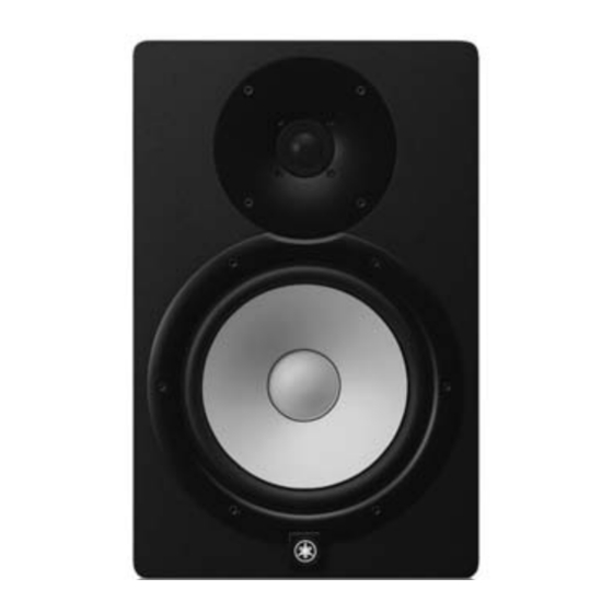
Yamaha Electone HS-8 Service Manual
2-2-5 Tone control
Measurement condition
The signal of -10dBu/500Hz is
input to INPUT 1(XLR), and
the output voltage is measured.
The signal of -10dBu is input to
INPUT 1(XLR), and the output
voltage is measured.
-2dB
-4dB
T h e s i g n a l o f
-2dB
-10dBu/500Hz is
input to INPUT
1(XLR), and the
output voltage is
-4dB
measured.
-2dB
-4dB
-2dB
+2dB
T h e s i g n a l o f
-2dB
- 1 0 d B u i s i n -
put to INPUT
1(XLR), and the
output voltage is
+2dB
measured.
-2dB
+2dB
Criteria
B1
SPOUT(LF)
B2
Red-Black
B3
B4
SPOUT(HF)
B5
Yellow-Blue
B6
The range of
-2.0±1.5dB
based on B1.
The range of
-4.0±1.5dB
based on B1.
The range of
-2.0±1.5dB
based on B2.
SPOUT(LF)
Red-Black
The range of
-4.0±1.5dB
based on B2.
The range of
-2.0±1.5dB
based on B3.
The range of
-4.0±1.5dB
based on B3.
The range of
-2.0±1.5dB
based on B4.
The range of
+2.0±1.5dB
based on B4.
The range of
-2.0±1.5dB
based on B5.
SPOUT(HF)
Yellow-Blue
The range of
+2.0±1.5dB
based on B5.
The range of
-2.0±1.5dB
based on B6.
The range of
+2.0±1.5dB
based on B6.
2-2-6 Output noise level
Measurement condition
Input no signal
Setting of operation elements
LEVEL control : MAX
INPUT (XLR) is grounded
through the resistor of 150Ω,
the noise level generated in the
output terminal is measured.
* Use the low-pass filter of 20kHz for the measurement.
2-2-7 Residual noise level
Measurement condition
Setting of operation elements
LEVEL control : MIN
The noise level generated in the
output terminal is measured.
* Use the low-pass filter of 20kHz for the measurement.
Initial setting
LEVEL
ROOM CONTROL
HIGH TRIM
LOW CUT
HIGH CUT
PHASE
POWER
HS8/HS7/HS5
Criteria
-59dBu or less
SPOUT (LF)
-65dBu or less
Red-Black
-59dBu or less
SPOUT (HF)
-63dBu or less
Yellow-Blue
Criteria
-59dBu or less
SPOUT (LF)
-65dBu or less
Red-Black
-59dBu or less
SPOUT (HF)
-63dBu or less
Yellow-Blue
HS8, HS7, HS5
MIN
0
0
OFF
19