Alemite 7531-4 Service Instructions Manual
Browse online or download pdf Service Instructions Manual for Water Pump Alemite 7531-4. Alemite 7531-4 6 pages. High pressure utility pump

TM
DESCRIPTION
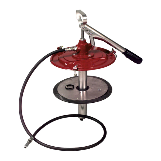
Utility pump Models 7531-4 and 7531-A4 are of the
hand-operated, lever-action type.
Model 7531-4 is designed to accommodate a 35 lb.
bucket. Model 7531-A4 operates from a 20 kg
container. See Figure 1.
Application of these units eliminates hand and paddle
filling methods, thus keeping lubricant clean and free
of any contamination when being applied.
The high-pressure pump provides ample pressure to
lubricate close-fitted bearings. Lubricant delivery is one
ounce (28.4 gms) per five strokes. The dynamic primer
aids priming in cold weather and enables the pump to
handle heavier greases more readily. All pressure gun
lubricants can be used. The follower plate prevents any
channeling of lubricant.
Each unit is equipped with a cover, follower plate, six
foot (1.8 m) lubricant hose, and hydraulic coupler. The
coupler provides a quick, leak-proof contact with the
hydraulic fitting and allows a wide sealing angle
connection.
SPECIFICATIONS
Pump Delivery .............. 1 oz. (28.4 gms) per 5 strokes
Pressure Developed ................... 3500 psi (241.4 Bar)
Finish ........................................ Maroon baked enamel
cover with other parts bright zinc
ASSEMBLY
To assemble either model pump, proceed as follows
using Figures 2, 3 and 4:
1. Place pump mechanism into cover 337729 and
secure with cap screws 77787 and hex nuts 77650.
2. Align link 328253-1 with holes in stud 338389 and
secure with pin 339961-1 and two retaining rings
171606 .
3. Align lever 314552 with pin hole in piston rod and
secure with nut 77650, screw 170699, and
lockwashers 77002.
670723
SERVICE INSTRUCTIONS
High Pressure Utility Pump
Alemite Corporation
www.alemite.com
167 Roweland Drive, Johnson City, Tennessee 37601
3/8" NPTF (f) Outlet
P
u
m
p
M
o
d
l e
C
o
n
a t
n i
7
5
3
1
4 -
3
5
b l
7
5
3
1
A -
4
2
0
K
g
Figure 1
Pump Models 7531-4 and 7531-A4
4. Align link 328253-1 and handle 318414 with hole in
lever 314552 and fasten with pin 339961-3 and two
retaining rings 171606.
INSTALLATION
To install pump, use Figures 2, 3, and 4 as reference
and proceed as follows:
1. Place follower plate 337665 or 328238-A4 on
lubricant surface in lubricant pail and press down until
lubricant is forced into center opening of follower. This
will remove any air pockets.
2. Insert pump tube through the center opening of the
follower plate. Secure with J-bolts 317102 and wing
nuts 170837 into brackets on cover 337729 when cover
is seated on pail.
3. Screw five-foot (1.5 m) lubricant hose with hydraulic
coupler into 3/8" lubricant-outlet check valve 317210.
7531-4
7531-A4
T
u
b
e
L
e
n
g
h t
r e
n I
c
h
e
s
C
m
1
2
3 -
8 /
"
3
1
4 .
1
5
1 -
3
1 /
6
"
4
0
2 .
7531-4 (12-03)
