Great Circle LCE01 Gebruiksaanwijzing - Pagina 8
Blader online of download pdf Gebruiksaanwijzing voor {categorie_naam} Great Circle LCE01. Great Circle LCE01 18 pagina's. Chipper shredder
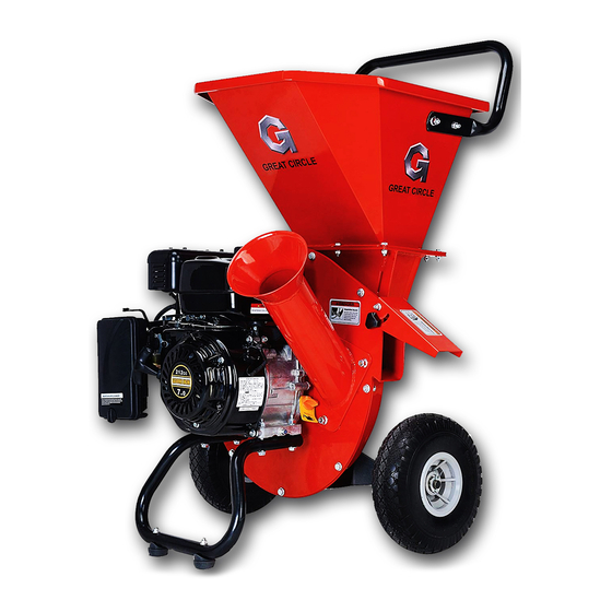
Install the Hopper (See Figure 5)
1. Set plate (G) with bolts through the aligned holes
2. Assembly the U shape plate (C) and put on plate (B)
3. Position the hopper (A) by aligning
the assembly holes and
fix by bolts (E)
4. Tight nuts (F) to secure
the guard assembly
to the hopper
GENERAL OPERATION
1. Be sure to read all information in the Safety and Operation sections before attempting to operate this unit.
Become familiar with all of the controls and how to stop the unit.
2. Check all hardware (bolts, screws, etc) before every use for tightness to be sure machine is in safe working
condition.
3. Overloading the equipment will shorten its life, and can cause mechanical failures.
Chipper Operation
The chipper is designed to handle tree limbs and branches up to approximately 3" (7,6 cm) in diameter. The
chipping knives also permit the processing of course organic matter like corn stalks. Tree branches must be
inserted large-end first into the chipper cone. Since occasional kick-backs may occur, always stand off to the side
of the unit. Allow the self-feeding action of the unit to draw the sticks in.
Shredder Operation
The shredder is designed to shred light brush, leaves, and other soft but bulky organic waste. As material (no
larger than 1/2 inch in diameter) is loaded into the shredder hopper it is pulled into the path of the hammers by air
flow.
Vacuum Attachment (Optional)
In addition to the chipper cone and hopper, loose debris may be processed by the Vacuum hose adapter kit.
Leaves may be raked directly into the leaf tray where vacuum action will draw them into the shredder. For
hard-to-reach areas, the nozzle and hose assembly may be used. The strength of the Vacuum may be changed
using the rotating sleeve on the nozzle.
Operating Location
1. Select an area with firm, level ground, covered by dirt or grass.
2. Do not operate on wet or slick surfaces, or near bystanders.
3. Locate and organize the materials to be processed so that you don't have to walk in front of the inlet or discharge
openings, and so you have adequate room to work safely.
6
Figure 5
Install the Hopper Guard (See Figure 6)
1. Position the hopper guard assembly (C) by aligning
the assembly holes with the holes in the hopper
2. Using the three M6 flange bolts (A) and nuts (D) to
secure the guard assembly (C) to the hopper.
Figure 6