ALLNIC AUDIO H-5500 Gebruikershandleiding - Pagina 6
Blader online of download pdf Gebruikershandleiding voor {categorie_naam} ALLNIC AUDIO H-5500. ALLNIC AUDIO H-5500 11 pagina's. Phono-stage preamplifier

C.
INPUTS
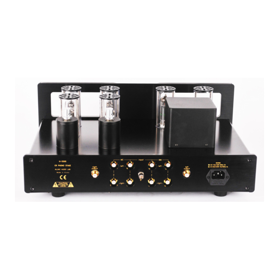
There are four (4) pairs of single-ended (RCA) inputs, two for Moving Coil (MC) cartridges and two for Moving
Magnet (MM) cartridges. These four pairs are located in the middle of the rear of the H-5500 with the ground screw
between the two MC pairs and the two MM pairs (See Figure 1). The input pairs are labeled MC 1 and 2 and MM 1
and 2, with the number of each pair on the vertical axis between the top (left channel) and bottom (right channel)
RCA input connectors. Facing the rear of the H-5500, the two left-hand pairs of inputs are the MC cartridge inputs,
with pair 1 closest to the centre ground screw. The two right-hand pairs of inputs are the MM inputs, with pair 2
closest to the centre ground screw and pair 1 next to the IEC connection.
When you are facing the front of the H-5500, the input connections are in the centre of the unit, with the MC
connections on the right and the MM connections to the left, next to the IEC connection.
The H-5500 has been designed and manufactured to work most synergistically with Allnic Audio products, including
line-stage preamplifiers, pre-phono stages and ZL Technology cable products.
D.
OUTPUTS
The H-5500 is equipped with one set of single-ended or "unbalanced" (RCA) outputs. Facing the rear of the H-5500,
the right channel RCA output connection is just to the left of the MC RCA input pairs (when facing the front of the H-
5500, to their right). Facing the rear of the H-5500, the left channel RCA output connection is just to the right of the
MC RCA input pairs (when facing the front of the H-5500, to their left (See Figure 1).
E.
MOVING COIL (MC) TRANSFORMER CONTROLS
Facing the front of the H-5500, the MC step up transformers are on the H-5500 deck immediately behind the four
E180CC tubes. The right channel transformer is on the right, closest to the outside edge of the chassis (See Figure
4). On top of each transformer cylinder, there is a rotating control (See Figure 3). Turn the control knob to select
from four gain factors: +22dB, +26dB, +28dB and +32dB. Combined with the H-5500's 40dB native gain, for MC
there is 62dB, 66dB, 68dB and 72dB of gain available. Each of the second set of indicators on the top of the
transformers marks the impedance tied to the gain setting diagonal to it. The impedance at each of ×13, ×20, ×26
and ×40 on the control knob is equivalent to 278Ω, 117Ω, 69Ω, and 29Ω and respectively. The impedance and gain
relationships are not user adjustable. You should experiment with the gain settings to find the best setting for your
cartridge. Use identical settings for both transformers to avoid channel imbalance.
INITIAL POWER-ON
Once you have your H-5500 in place and all connections have been made to your turntable and preamplifier, you are
ready to turn on the power for your H-5500. Before you power up the H-5500, be sure you have:
•
removed ALL the cushion materials from inside the tube chimneys
•
turned the volume down or muted your preamplifier
•
muted the H-5500 by ensuring that the button switch labeled "mute" on the right-hand side of the front panel
of the H-5500 is in the "out" position (i.e., it is not "depressed") (See Figure 2)
6
