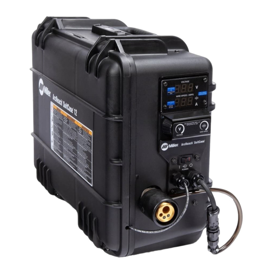
Miller ArcReach 16 Gebruikershandleiding - Pagina 41
Blader online of download pdf Gebruikershandleiding voor {categorie_naam} Miller ArcReach 16. Miller ArcReach 16 48 pagina's.

Wire stubbing on low end using a con-
stant current power source or feeder
resets.
Gas does not flow or does not stop
flowing; wire feeds.
Wire remains energized after trigger is
released.
Gun trigger is pressed, gas does not
flow, wire is not energized, wire feeds.
Display on Meter Board PC 22 does
not light.
Segments on Meter Board PC 22 are
missing.
Weld voltage on Meter Board PC 22 is
not accurate.
While not welding - Voltage display
shows three dashes.
While not welding - Voltage display
shows CC.
Weld amperage on Meter Board PC
22 is not accurate.
Software and weld time information on
Meter Board PC 22 is not accurate.
When associated to an ArcReach con-
trol or ArcReach compatible power
source - Voltage displayed on feeder
does not match voltage on power
source.
Feeder will not associate to an Ar-
cReach control or ArcReach compati-
ble power source.
�
Complete Parts List is available at www.MillerWelds.com
Have Factory Authorized Service Agent check Control board PC1.
Check DIP switch settings on Meter Board PC22 (see section 5-13)
Ensure that CC/CV switch in feeder is in CC position (see Section 6-1).
Increase power source inductance setting if available.
Increase output setting of power source or decrease wire feed speed.
Clear blockage in gas hose or replace hose.
Clear blockage in welding gun.
Clear blockage in filter (see Section 7-3).
Check gas valve.
Check coil voltage and connections of gas valve GS1. Check continuity of coil. Replace GS1 if
necessary.
Have Factory Authorized Service Agent check Control board PC1.
Check setting of trigger hold switch.
Check contactor W1 to see if contacts are frozen closed.
If a welding arc is not established in 3 seconds after the gun trigger is activated, the unit will feed wire
without energizing the contactor or gas valve. The unit will feed approximately 35 feet (10.7 meters)
of wire, then stop feeding. This is to prevent complete despoolling of the wire, as in the case of a
damaged gun.
Have Factory Authorized Service Agent check Control board PC1.
Replace Meter Board PC 22.
Replace Meter Board PC 22.
Weld voltage on Meter Board PC 22 will show weld voltage at the feeder. Due to voltage drops in the
weld cables, weld voltage at the feeder will not match weld voltage at the welding power source. Due
to averaging of weld voltage, if weld time is less than 8 seconds the displayed weld voltage at the
feeder may not be accurate.
Check Motor Control PC1 and connections, replace if necessary.
This is normal when unit is connected to a Non-ArcReach compatible power source (see Section 6-
1).
Unit is connected to but not associated to an ArcReach control or ArcReach compatible power
source (see Section 5-5).
This is normal when the CC/CV switch is set to CC mode (see Section 6-1).
Amperage displayed at feeder is approximate. Refer to power source for actual amperage(see Sec-
tion 5-13)
Check DIP switch settings on Meter Board PC 22 (see Section 5-13).
Check transducer HD1 and connections, and replace if necessary.
Check Motor Control PC1 and connections, replace if necessary.
Check DIP switch settings on Meter Board PC 22 (see Section 5-13).
Check Motor Control PC1 and connections, replace if necessary.
Preset voltages between the feeder and welding power source should be within 0.5 volt of each
other.
When associated to an ArcReach control, verify that the ArcReach control is configured properly(see
ArcReach control owner's manual).
While welding the voltage displayed at the feeder is the weld voltage at the feeder. The voltage dis-
played at the power source is the weld voltage at the power source. These two voltages will not
match due to voltage drops in the weld cables.
Due to averaging of the weld voltage, if weld time is less than 8 seconds the displayed weld voltage
at the feeder may not be accurate.
Check Motor Control PC1 and connections, replace if necessary.
Follow associating wire feeder procedure (see Section 5-4).
CC/CV switch must be set to CV to associate to ArcReach control or ArcReach compatible power
source (see Section 6-1)
Ensure that the ArcReach compatible power source Mode Switch is set correctly, see welding power
source Owner's Manual.
OM-278792 Page 35
