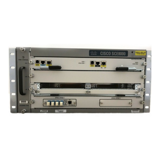
Cisco SCE8000 GBE Procedures voor verwijdering en vervanging - Pagina 8
Blader online of download pdf Procedures voor verwijdering en vervanging voor {categorie_naam} Cisco SCE8000 GBE. Cisco SCE8000 GBE 36 pagina's. 10gbe platform
Ook voor Cisco SCE8000 GBE: Snelstarthandleiding (25 pagina's), Configuratiehandleiding (18 pagina's), Installing (21 pagina's)

Installing a DC-Input Power Supply
Grasp both power supply handles, as shown in
Step 7
the chassis.
Figure 9-4
Handling a DC-Input Power Supply
P W R -2
7 0 0 -D C
/4
Power Supply 1
Installing a DC-Input Power Supply
This section covers the DC-input power supply installation procedure for the Cisco SCE 8000 chassis.
The DC return is to remain isolated from the system frame and chassis (DC-I).
Note
Warning
Before performing any of the following procedures, ensure that power is removed from the DC circuit.
Statement 1033
Power supply ground is required. Install the PWR-2700-DC/4 power supply ground as described in this
Step 1
procedure.
The system ground connection with the PWR-2700-DC/4 power supply in a Cisco SCE 8000 is provided
Note
by the PWR-2700-DC/4 power supply ground. Additionally, you can connect a system (earth) ground.
You must always connect the PWR-2700-DC/4 power supply ground.
Caution
Cisco SCE8000 10GBE Installation and Configuration Guide
9-8
Power Supply 2
(redundant)
P W R -2
7 0 0 -D C
/4
+V E- 1
-V E- 1
+V E- 2
-V E- 2
AL L FA
ST EN ER
PR IO R
S MU ST
TO OP
BE FU
ER AT ING
LL Y EN
TH E PO
WE R SU
+V E- 1
INP UT
1
INP UT
+V E- 1
OK
2
FA N
OK
OU TP UT
48 V-6 0V
-V E- 1
OK
48 V-6 0V
FA IL
=4 0A
=4 0A
-V E- 1
+V E- 2
+V E- 2
-V E- 2
-V E- 2
AL L FA
ST EN ER
PR IO R
S MU ST
TO OP
BE FU
ER AT ING
LL Y EN
TH E PO
GA GE
D
WE R SU
PP LY
Figure
9-4, and slide the power supply completely out of
+V E- 1
INP UT
1
INP UT
OK
2
FA N
OK
OU TP UT
48 V-6 0V
OK
48 V-6 0V
FA IL
=4 0A
=4 0A
-V E- 1
+V E- 2
-V E- 2
GA GE
D
PP LY
Chapter 9 Removal and Replacement Procedures
OL-26784-02
