Yamaha Electone HS-8 Servicehandleiding - Pagina 9

Blader online of download pdf Servicehandleiding voor {categorie_naam} Yamaha Electone HS-8. Yamaha Electone HS-8 43 pagina's. Serie hs monitor da studio alimentato e subwoofer alimentato
Ook voor Yamaha Electone HS-8: Gebruikershandleiding (2 pagina's), Gebruikershandleiding (2 pagina's), Gebruikershandleiding (20 pagina's), Gebruikershandleiding (20 pagina's), Gebruikershandleiding (21 pagina's), Gebruikershandleiding (20 pagina's), Gebruikershandleiding (20 pagina's), Gebruikershandleiding (20 pagina's), Gebruikershandleiding (20 pagina's), Gebruikershandleiding (20 pagina's), Gebruikershandleiding (20 pagina's), Gebruikershandleiding (20 pagina's), Gebruikershandleiding (20 pagina's), (Engels) Gebruiksaanwijzing (20 pagina's)
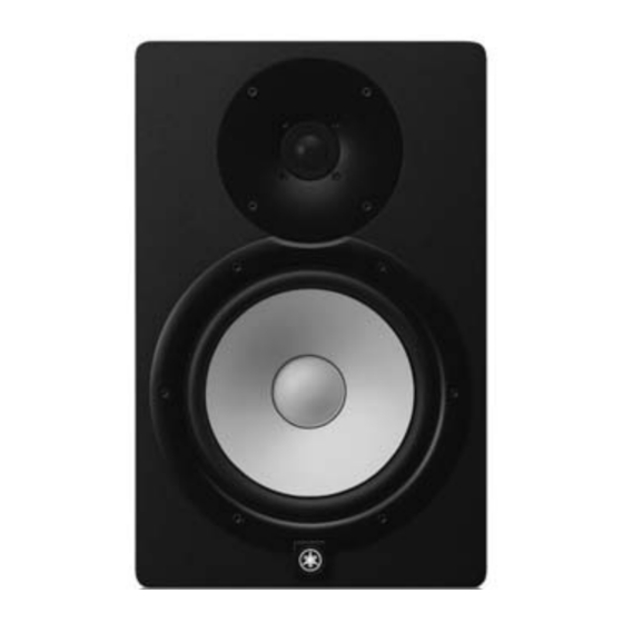
Yamaha Electone HS-8 Servicehandleiding
LED connector assembly
(LED束線)
* The connector in the photo is the
initially produced model. The color of
the connector has been changed to
black.
※ 写真は、 初期生産品です。生産途中か
 
らコネクターは、黒色に変わります。
Photo 3 ( 写真3)
Hotmelt
(ホッ トメルト)
LED connector assembly
(LEDW)
LED
(LED束線)
Photo 4 ( 写真4)
Disassembly of AMP Assembly
*
Before disassembly, remove the AMP assembly in
advance. (See procedure 3 on page 8)
5.
AMP Circuit Board
(Time required: About 8 minutes)
5-1
Remove binding tie (A) and (B). Disconnect the
connector assemblies from the connector CN202 (4P)
of the TR circuit board. (Fig. 4)
*
Install as before binding tie (A) and (B) was removed.
(Fig. 4)
<AMP ASSEMBLY ( アンプ Ass'y)>
<HS8, HS7>
Photo 4
(写真4)
LEDW circuit board (LEDW シート)
LED connector assembly
(LED束線)
Binding tie (A)
(インシュロックタイ (A) )
Binding tie (B)
(インシュロックタイ (B) )
Connector CN202 (4P)
(コネクターCN202(4P))
TR
AMP
AMP assembly
(アンプ Ass'y)
Photo 3
(写真3)
LED connector assembly
(LED束線)
Fig. 3 ( 図3)
アンプ Ass'y の分解
  ※ 
分解の前に、 あらかじめアンプ Ass'y を外しておきます。
(8 ページの 3 項参照)
5. 
AMP シート
 
(所要時間:約 8 分)
5-1 
インシュロックタイ (A) とインシュロックタイ (B)
を外し、TR シートのコネクター CN202(4P) から
束線を外します。 (図 4)
  ※   取付けるときには、 インシュロックタイ(A)とインシュ
ロックタイ(B)を取り外す前と同じように取り付けて
ください。 (図 4)
<HS5>
Binding tie (A)
(インシュロックタイ (A) )
Fig. 4 ( 図4)
HS8/HS7/HS5
[100] x 10
Priority screw (1st)
(優先ネジ (1) )
Priority screw (2nd)
(優先ネジ (2) )
color : red
(赤)
Solder side
(パターン側)
color : white
(白)
Soldering (ハンダ付け)
Binding tie (B)
(インシュロックタイ (B) )
TR
Connector CN202 (4P)
(コネクターCN202(4P))
AMP
LED
9