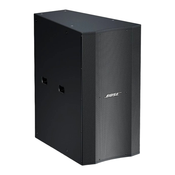
Bose Panaray LT 9402TM WR Instrukcja serwisowa - Strona 14
Przeglądaj online lub pobierz pdf Instrukcja serwisowa dla Głośniki Bose Panaray LT 9402TM WR. Bose Panaray LT 9402TM WR 27 stron. Weather resistant

Panaray
Item
Number
1
Kit, Grille Screw, TA4x15 (14 screws per kit)
Black
White
2
Washer, Flat, 4x9x0.8mm
3
Grille Assy (with screws & logo assy.)
Black
White
4
EVA Gasket, V2 Cover
5
V2 Cover
6
Gasket, Rubber, 262x19x1, Blk
7
Screw, V2 Cover, 6x30M, D=10, Stainless, Blk
8
V2 Assembly
9
Washer, Nylon, 12x6.6x1mm, Blk
10
Screw, VEE-Two Assy.
11
Screw, Input Panel, TM4x15
12
Input Panel with Crossover PCB, Black
13
Gasket, Input Panel
14
Screw, Compression Driver, 6x30mm, SS, Blk
15
Compression Driver Assy
16
Disk, Alignment, Compression Driver
17
Gasket, Compression Driver
18
- Insert, Rigging, 3/8x16 thread
- Screw, 9.5x20mm, Stainless, Blk
- Washer, PVC, 15.5x9.6x0.4mm
19
Gasket, grille
20
Logo Kit with tape, fastener and spring
Black
White
-
Compression Driver Replacement Diaphragm
-
Screw, Hang Point, 3/8" x 16
20
1
2
Figure 9. Panaray LT 9402 WR Loudspeaker Exploded View
MAIN PART LIST
®
LT 9402
TM
WR Loudspeaker (see Figure 9)
Description
19
18
3
Bose
Number
297502
297503
322822-010S
298584
322820-010S
298172
322824-010S
276860
263912
263911
297504
297505
276861
298591
17
16
4
5
6
14
®
Part
Qty
Note
1
-
10
1
-
1
1
-
2
-
2
2
-
8
-
8
-
12
1
-
1
-
4
1
1
1
-
16
-
16
-
32
1
1
16
15
14
13
12
11
10
7
8
9
4
4
