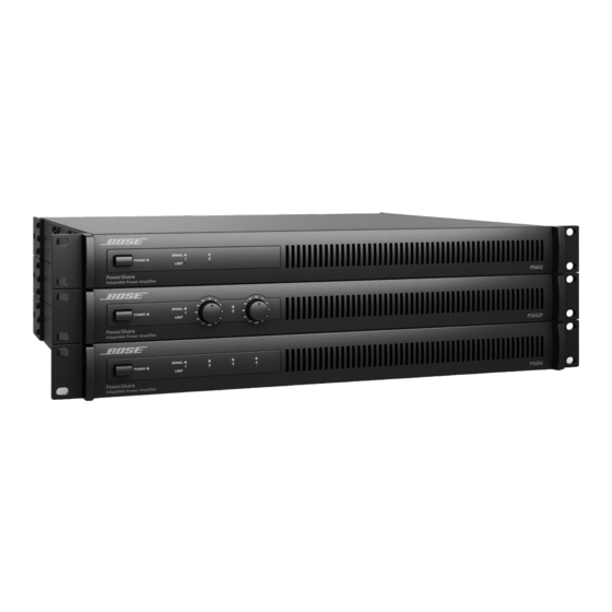
Bose PowerShare PS604A Instrukcja instalacji i obsługi - Strona 25
Przeglądaj online lub pobierz pdf Instrukcja instalacji i obsługi dla Wzmacniacz Bose PowerShare PS604A. Bose PowerShare PS604A 40 stron. Adaptable power amplifiers

pro.Bose.com
Importance of Proper Ventilation
For placement of the amplifier, keep the following in mind:
• Make sure that air can circulate freely from left to right for adequate ventilation. There are vents on the sides.
• The temperature of the rack should be controlled to ensure that amplifiers are not exposed to ambient temperatures
exceeding 40° C (104° F).
• Do not cover or block amplifier vents.
• Do not place the amplifier in an enclosed space, such as a cabinet.
• Make sure the chassis is protected from heat and kept away from direct heat sources, such as heating vents and
radiators.
• The two fans in each amplifier run together at a variable speed. The fans will spin faster as the internal temperature
increases in order to keep the amplifier out of thermal shutdown when operating at 40° C (104° F) or less, and at one-
third (1/3rd) continuous power or less.
CAUTION: Do not allow the chassis to exceed the maximum operating temperature of 40° C (104° F). Be aware of
conditions in an enclosed rack that may increase the temperature above room-ambient conditions. If the amplifier becomes
too hot, it will go into a thermal protection mode and mute all outputs.
Mute with Standard Contact Closure
The amplifier is designed to mute all outputs either when the MUTE contacts are shorted together, or when the MUTE
contacts are opened, depending on the amplifier configuration.
The default state is Normally Open (NO), where a short across the mute connector will mute all outputs. The mute polarity
can be inverted to Normally Closed (NC), where an open across the mute connector will mute all outputs, using the
PowerShare Editor software. See the Software Interface section for more details.
NOTE: All Limit LEDs will blink red when the amplifier is muted from software, or from the rear panel mute connector.
Use the included 2-pin Euroblock.
Figure 8. Amplifier mute contact closure
Installation Guide
Installation and Operation
MUTE
English 25
