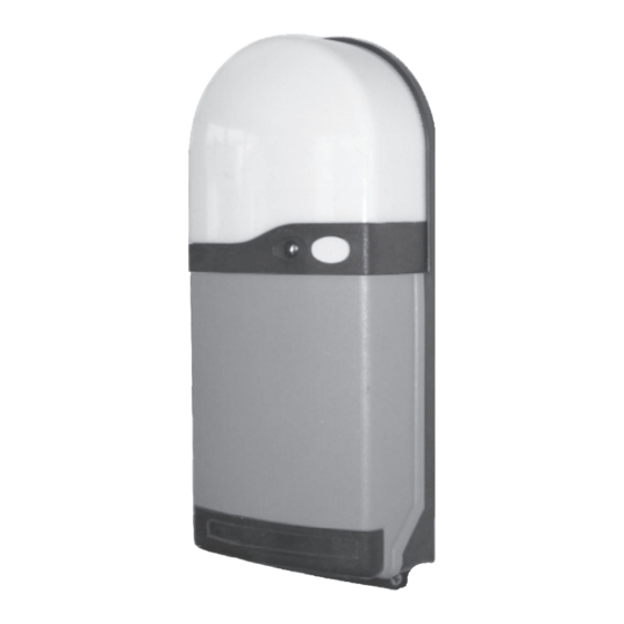
Ansa RS-1 Instrukcja instalacji i obsługi - Strona 7
Przeglądaj online lub pobierz pdf Instrukcja instalacji i obsługi dla Jednostka sterująca Ansa RS-1. Ansa RS-1 12 stron. Ansa roller door remote control unit

- 1. Table of Contents
- 2. General Description
- 3. General Operation
- 4. Multi Channel Keyfobs
- 5. Fitting the RS-1 Control Unit
- 6. Electrical Connections
- 7. Photoelectric Cell Safety System (Optional)
- 8. Light Grid Safety System (Optional)
- 9. Alarm System (Optional)
- 9. Figure 16
- 9. Commissioning
- 9. Adding/Deleting Transmitters & Wireless Access Controls
- 9. Dip Switch Options & Special Settings
- 9. Technical Specifications
7
LG-1 Light Grid Safety System (optional)
7.1 Function
The ANSA LG-01 Light Grid is an active safety system designed to monitor the closing operation of Roller Doors equipped with an ANSA RS-1
control unit. The equipment comprises an emitter (Tx) track and receiver (Rx) track which are mechanically fixed directly to the door guide
tracks and electrically connected (low voltage) to the ANSA remote control unit. The emitter and receiver tracks contain multiple
photoelectric sensors which build up a grid of 34 infra red beams covering door entrances up to 6 metre wide and 1.8 metres high. The safety
grid detects obstructions in the path of a closing door preventing closure of the door or safety reversing the closing movement. The compact
and robust design with a cross section of only 12mm x 16mm provides minimal intrusion into the garage space Status LED indicators are fitted
to both the transmitter, receiver and ANSA remote control units for easy installation and set-up.
Figure 12
blue plug
yellow
LED
indicator
receiver
(rx)
track
leave 10mm
clearance under
the grid track to
the floor
Fig. 13
Fig. 14
spacers to prevent
curtain activating light grid
Fig. 15
25mm
7.3 How to Align the Safety Grid System
The Safety Grid System is virtually self aligning. Correct alignment is indicated when the green LED fitted to the transmitter track and the
yellow LED fitted to the receiver track are illuminated.
7.4 Testing
Obstructing the Light Grid should cause the receiver track yellow LED to switch off and at the same time the red LED should flash quickly
confirming satisfactory operation. Once a month
Page 6
opening
structure
door guides
25mm
7.2 Installation
The transmitter (Tx) with white cable connector and the receiver
connection
lead
(Rx) with the blue connector can be fitted to either door guide
channel with the connection leads at the top. The 'black eyes' in the
tracks are the optical elements which must face each other. Fix the
tracks to the rear of the door guides leaving a 10mm clearance to
the floor. Ensure that no sunlight shines directly into the optic
lenses.
If necessary make allowance for uneven floors which could block
white plug
green LED
the bottom infrared beam and raise the transmitter and receiver
indicator
tracks slightly to allow for any 'high spots'.
The transmitter and receiver are fixed to the door guide each using
the 3.5mm diameter self drilling fixings provide. Secure the tracks
transmitter
(tx)
securely ensuring they are plumb. Use only the fixing holes
track
provided in the grid tracks. Do not drill additional holes in the
profiles or bend ot twist the grid tracks.
Ensure that the connection leads are well fastened and rooted
leave 10mm
using the cable fittings supplied or alternatively plastic cable ducting
clearance under
the grid track to
(not supplied). Do not bend the cables or expose them to tension.
the floor
Standard fixing arrangement for doors internally face fixed or
reveal fixed. Suitable for doors not subject to high wind loading or
double width
Note; For double width doors or doors subject to high wind
loading, use plastic cable ducting or similar (not supplied) to space
the grid tracks away from the door guides to prevent any curtain
deflection from operating the light grid system
For externally fitted doors a 25mm guide overhang is
recommended to protect the emitter and receiver tracks. The
tracks can be fixed to the opening structure using suitable fixings –
but avoid bending or drilling the track when installing.
Alternatively
The emitter and receiver tracks may be installed inside the
building using the wall plugs and fixings supplied – but avoid
bending or drilling the track when installing.
