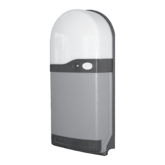
Ansa RS-1 Instrukcja instalacji i obsługi - Strona 9
Przeglądaj online lub pobierz pdf Instrukcja instalacji i obsługi dla Jednostka sterująca Ansa RS-1. Ansa RS-1 12 stron. Ansa roller door remote control unit

- 1. Table of Contents
- 2. General Description
- 3. General Operation
- 4. Multi Channel Keyfobs
- 5. Fitting the RS-1 Control Unit
- 6. Electrical Connections
- 7. Photoelectric Cell Safety System (Optional)
- 8. Light Grid Safety System (Optional)
- 9. Alarm System (Optional)
- 9. Figure 16
- 9. Commissioning
- 9. Adding/Deleting Transmitters & Wireless Access Controls
- 9. Dip Switch Options & Special Settings
- 9. Technical Specifications
9
Commissioning
The tubular geared motor supplied with your door has integral electro-mechanical limit switches that cut off the power to the door
motor when the door is at the fully open or fully closed position. For reliable & safe operation of the door,
must be accurately set in accordance with information supplied by the door manufacturer. The following general guidelines
may be helpful.
Before you operate the door electrically you may want to operate the door slowly using the manual override provided
to ensure that the door will not catch on any protrusions as it travels up and down.
Somfy Motor Drives have the advantage of commissioning using the manual override to set the motor limits and to make final
adjustments which provide far greater control of the door as it travels up and down.
9.1 Doors Equipped with Somfy Motor drives
Left hand
motor
installation
White limit button
Close / Down
Yellow limit button
Open / Up
To set the motor limits, remove the cap covering the white & yellow limit switch buttons and fully press in both switches (they
·
will lock in the depressed position).
Wind the door down using the override handle so that the door locking system is set in accordance with the door manufacturers
·
instructions. Press and release the door close / down limit button so that it 'pops out' to memorise this door close position.
Wind the door open using the override handle so that the door fully open position is set in accordance with the door manufacturers
·
instructions. Press and release the door open / up limit button so that it 'pops out' to memorise this door open position.
Note - Always replace the limit switch cover cap once the limits are set.
9.2 Doors equipped with Tubular Motor Drives with Screw Limit Switch Adjusters
Left hand
motor
installation
door open &
door close screw
limit adjusters
Adjustment of screw type limits is carried out with the power supply switched on.. Use extreme caution to avoid personal injury
·
or damage to the door and
Adjustment is carried out by rotating two screw adjusters fitted to the motor. Carefully study the door manufacturer's instructions
·
so that the correct open and close adjuster is identified and the correct rotation of each adjuster to increase or decrease door travel
is known.
Use the override handle to position the door half open. The RS-1 Control button is used to control
·
the door (refer to Section 2.1) and Option Dip switch No. 3 on the RS-1 PCB will need to be switched
on when carrying out limit switch adjustments.
Open and close the door ensuring that at no time does the door curtain raise out of the door guides
·
or over-travel when closing which could cause personal injury or damage to the door.
Carry out fine adjustment of the limit switches in accordance with the door manufacturers
·
instructions, noting that the door could move slightly when the adjusters are being rotated.
NOTE
- Ensure that the motor direction matches the open and close RS-1circuit board LED's, if necessary switch off the mains power supply
and interchange the motor cables at L1 and L2.
repetitive use, causing the motor to cut out. If the thermal trip operates wait approximately 10 minutes for the motor to return to normal
operating temperature. When the limit switches are correctly set turn off Dip switch 3 for normal operation. See fig 19
Page 8
close
open
always follow the door manufacturers specific instructions.
Note:
the motor unit has an inbuilt thermal trip which activates if the motor gets too hot after
Figure 17
Figure 18
the motor limit switches
Right hand
motor
installation
Yellow limit button
Close / Down
White
limit button
Open / Up
Right hand
motor
installation
close
open
door open &
door close screw
limit adjusters
Figure 19
Switch On to set limits
1
2
3
4
5
6
Switch Off when
limits are set
