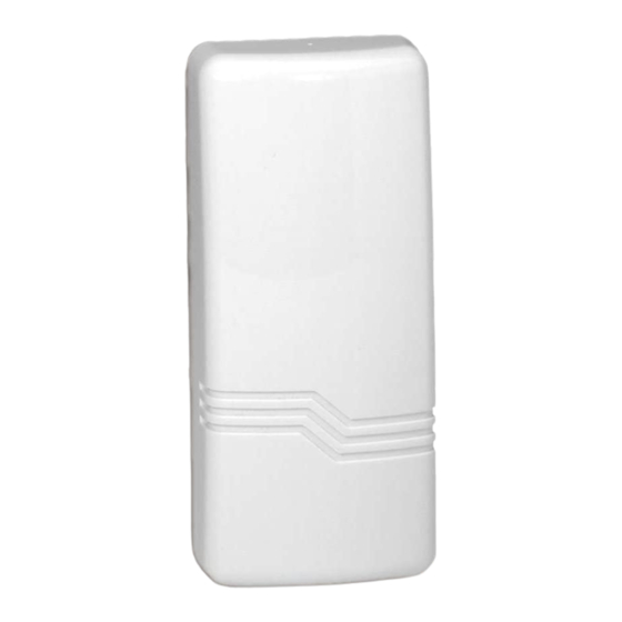
ADEMCO 5817CB Instrukcje instalacji - Strona 2
Przeglądaj online lub pobierz pdf Instrukcje instalacji dla Nadajnik ADEMCO 5817CB. ADEMCO 5817CB 4 stron. Wireless commercial /
household transmitter
Również dla ADEMCO 5817CB: Skrócona instrukcja obsługi (2 strony), Instrukcja instalacji i konfiguracji (2 strony), Instrukcje instalacji (2 strony), Instrukcja instalacji i konfiguracji (2 strony)

6. Attach the case back to the mounting plate by sliding the keyhole slots in the case
back down onto the mounting plate's holding posts. The locking tab will click as the case
back locks in place. To disengage the unit from an installed mounting plate, insert a
small screwdriver into the mounting plate release hole, push down to retract the locking
tab, and push upward on the unit to disengage from posts.
Set the DIP switch (after the control panel has enrolled the transmitter's input IDs) for
7.
the desired primary loop characteristics, as described in the table below.
SWITCH
SETTING
ON
REPEATING
TRANSMISSION
(every 4 sec.)
UPON PRIMARY
LOOP FAULT
Use for high priority
alarm, such as fire.
SINGLE
OFF
TRANSMISSION
PER PRIMARY
LOOP CHANGE-
OF-STATE
Notes:
a. In order for the control panel to enroll the transmitter, the DIP switches must
be set to OFF – ON – ON – OFF (see Diagram 2).
b. The Auxiliary loops are not affected by the DIP switch settings.
UL REQUIREMENT
1. If using one of the panel revisions shown in the following table, and programming the
5817CB as an Entry/Exit zone, you must enroll the tamper loop (loop 4) as a separate
zone, programmed for 24-hour response (e.g., zone type 5 Trouble-by-day/Alarm-by-
night).
Model #
FA1600C
Vista-32FB
Vista-128FB
Vista-128B
2. For UL Commercial Burglary installations, this transmitter must be used in conjunction
with the 5881ENHC RF Receiver.
WIRING CONNECTIONS
Connect the loop wiring to the unit's terminals before installing the battery (see Diagram 2).
Notes :
a. Primary loop 1 is a supervised loop and must have an end-of-line (EOL) resistor
(470K ohms, supplied) placed across the last sensor. Additionally, for Primary
loop 1, a contact device may not be installed more than 20 feet from the
transmitter.
b. If loop 2 is not going to be used, the magnet is not necessary.
c.
If loop 3 is not going to be used, no connection is needed across its terminals.
For UL household burglary and fire installations, the loop 3 contact device (if
used) may not be more than 3 feet from the transmitter.
BATTERY INSTALLATION/REPLACEMENT
1. Remove the transmitter's cover as described in Mounting Step 1.
2. Observe correct polarity and insert the battery provided into the battery holder
(see Diagram 2). Take care not to bend the antenna.
PRIMARY LOOP OPTIONS TABLE
1
SWITCH MUST
ALWAYS BE
IN THE
ON
POSITION
Rev.
EPROM P/N
8
(WAVIS150FA-18)
3
(WAVIS32FB-13)
4
(WAVIS128FB-14)
3
(WAVIS128B-13)
DIP SWITCH POSITION
2
SWITCH MUST
ALWAYS BE
IN THE
POSITION
- 2 -
3
SWITCH MUST
ON
4
ALWAYS BE
IN THE
OFF
POSITION
