DBI SALA NANO-LOK SRL 3101264 Instrukcja obsługi - Strona 8
Przeglądaj online lub pobierz pdf Instrukcja obsługi dla Czujniki bezpieczeństwa DBI SALA NANO-LOK SRL 3101264. DBI SALA NANO-LOK SRL 3101264 15 stron. Self retracting lifelines

EN
This product is part of a personal fall arrest, work positioning, or rescue system. These instructions must be provided to
the user of this equipment. The user must read and understand these instructions before using this equipment. Manufacturer's
instructions must be followed for proper use and maintenance of this equipment. Alterations or misuse of this product or
failure to follow instructions may result in serious injury or death. If this product is resold outside the original country of
destination, the re-seller must provide these instructions in the language of the country in which the product will be used.
IMPORTANT:
If you have questions on the use, care, or suitability of this equipment for your application, contact Capital Safety.
IMPORTANT:
and maintenance log of this manual.
DESCRIPTION:
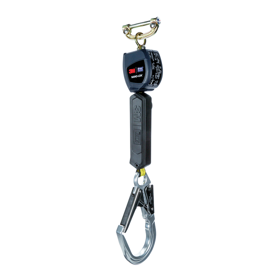
The Nano-Lok™ SRLs are 6 ft. (2 m) Lanyards, equipped with an in-line Load Indicator, which retract into a Thermoplastic
mounting on a Full Body Harness (see Figure 1). The Nano-Lok™ SRL automatically locks at the onset of a fall to arrest the
fall, but pays out and retracts lifeline during normal movement by the attached user. Figure 2 illustrates the following key
components of the base Nano-Lok™ Self Retracting Lifeline (SRL): Swivel (A), Swivel Eye (B), Integral Connector (C), Housing
(D), Web Lifeline (E), Load Indicator (F), iSafe™ RFID Tag (G), Lifeline Hook (H).
1.0 APPLICATIONS
1.1
PURPOSE: Capital Safety Self Retracting Lifelines (SRLs) are designed to be a component in a personal fall arrest system
(PFAS). Figure 1 illustrates SRL models covered by this instruction manual. They may be used in most situations where
a combination of worker mobility and fall protection is required (i.e. inspection work, general construction, maintenance
HOT WORK:
1.2
STANDARDS:
1.3
TRAINING: This equipment is intended to be used by persons trained in its correct application and use. It is the responsibility of the
user to assure they are familiar with these instructions and are trained in the correct care and use of this equipment. Users must also
be aware of the operating characteristics, application limits, and the consequences of improper use.
2.0 LIMITATIONS & REQUIREMENTS
Always consider the following limitations and requirements when installing or using this equipment:
2.1
CAPACITY: SRLs are designed for use by one person with a combined weight (person, clothing, tools, etc.) not exceeding
310 lbs (141 kg).
At no time shall more than one person connect to a single SRL for fall arrest applications.
2.2
ARREST FORCE: SRLs documented in this instruction meet the following Arrest Force values:
Average Arresting Force
900 lbs (4.0 kN)
2.3
ANCHORAGE: Anchorage structure for the SRL must be capable of supporting loads up to 2,248 lbs (10 kN). Anchor
devices must conform to EN795.
2.4
RESCUE PLAN: When using this equipment, the employer must have a rescue plan and the means at hand to implement
it and communicate that plan to users, authorized persons, and rescuers.
2.5
INSPECTION FREQUENCY: The SRL shall be inspected by the user before each use and, additionally, by a Competent
Person
1
other than the user at intervals of no more than one year
Maintenance Log" (Table 1). Results of each Competent Person inspection should be recorded on copies of the "Inspection &
Maintenance Log" (Table 1) or recorded with the i-Safe™ system (see Section 5).
2.6
LOCKING SPEED: Situations which do not allow for an unobstructed fall path should be avoided. Working in confined
or cramped spaces may not allow the body to reach sufficient speed to cause the SRL to lock if a fall occurs. Working on
slowly shifting material, such as sand or grain,may not allow enough speed buildup to cause the SRL to lock. A clear path
is required to assure positive locking of the SRL.
2.7
NORMAL OPERATIONS: Normal operation will allow the full length of the lifeline to extend and retract with no hesitation
when extending and no slack when retracting as the worker moves at normal speeds. If a fall occurs, a speed sensing
brake system will activate, stopping the fall and absorbing much of the energy created. For falls which occur near the
end of the lifeline travel, a reserve lifeline system or Load Indicator has been incorporated to assure a reduced impact fall
arrest. If the SRL has been subjected to fall forces, it must be taken out of service and inspected (see Section 5). Sudden
or quick movements should be avoided during normal work operation, as this may cause the SRL to lock up.
1 Competent Person:
hazardous, or dangerous to employees, and who has authorization to take prompt corrective measures to eliminate them.
2 Inspection Frequency:
inspections.
Fire resistant "Hot Work" models are available for welding, foundry work, etc. where the SRL may be
One who is capable of identifying existing and predictable hazards in the surroundings or working conditions which are unsanitary,
Extreme working conditions (harsh environments, prolonged use, etc.)may require increasing the frequency of competent person
Maximum Arresting Force
1,350 lbs (6.0 kN)
2
. Inspection procedures are described in the "Inspection &
8
