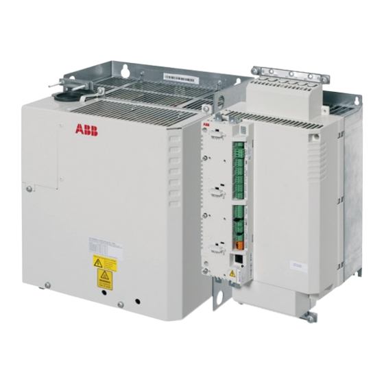
ABB ACSM1-204 Instrukcja szybkiej instalacji i uruchomienia - Strona 5
Przeglądaj online lub pobierz pdf Instrukcja szybkiej instalacji i uruchomienia dla Urządzenia przemysłowe ABB ACSM1-204. ABB ACSM1-204 15 stron. Regen supply module
Również dla ABB ACSM1-204: Podręcznik (16 strony)

Mechanical installation
Fasten the regen supply module to the mounting base using screws through the four
mounting holes. Frame A and B can be mounted onto a DIN rail, but it is
recommended to fasten the modules to the mounting base also by two screws
through the lower mounting holes.
Fasten the regen filter module as instructed in WFU-xx Regen Filter Module
Installation Guide.
Installing the power cables
Connection diagram
Input power line
L1 L2 L3
PE
1)
2)
PE
L1 L2 L3
WFU-xx
U2 V2 W2 PE
Connection procedure
Cabling examples are presented on page 7. Tightening torques are presented on
page
8
and at appropriate points in the text. For power cable connections in an
installation example, see
• Attach the terminal blocks included to the regen supply module.
• Frame sizes C and D only: Remove the two plastic connector covers at the top
and bottom of the regen supply module. Each cover is held by two screws.
• On IT (ungrounded) systems and corner-grounded TN systems, remove the
screw labeled VAR located close to the supply terminals. Also, remove the screws
Quick installation and start-up guide – ACSM1-204 5
3)
U1 V1 W1
UDC+UDC-
ACSM1-204
U2 V2 W2 PE
R+ R-
4)
Appendix
on page 13.
No.
Description
1
Main disconnector and fuses (switch fuse)
2
Main contactor
3
DC fuses
4
Brake resistor (optional)
3)
U1 V1 W1
UDC+UDC-
ACSM1-04
U2 V2 W2 PE
PE
V1 W1
U1
M
~3
R+ R-
