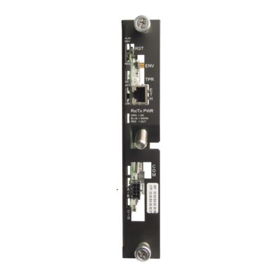
Alpha Technologies AlphaNet DSM3x Instalacja i skrócona instrukcja obsługi - Strona 4
Przeglądaj online lub pobierz pdf Instalacja i skrócona instrukcja obsługi dla Jednostka sterująca Alpha Technologies AlphaNet DSM3x. Alpha Technologies AlphaNet DSM3x 6 stron.

Installation Procedure, continued
5. If the Inverter Module is already equipped with a Communication Module,
remove it by loosening the two Phillips captive screws (Fig. 5, item A).
The following steps apply to both new installations or removal/replacement
of existing transponders:
6. Connect the 18-pin jumper (Fig. 6) supplied with the transponder into the
header on the back of the DSM3 Series circuit board (Fig. 7).
CAUTION!
Use of the incorrect jumper will cause damage to the
Transponder. Fig. 6 shows the correct 18-pin jumper.
7. Line up the 18-pin jumper with the header on the Inverter Module and connect
the unit to the Inverter Module (Fig. 8).
8. Fasten the Transponder to the Inverter Module by tightening the two captive
screws. It is recommended the screws be tightened alternately, a few turns
at a time so the transponder aligns in parallel to the Inverter Module.
Fig. 6, 18-pin Jumper
(Alpha p/n 540-286-19)
9. Reinstall the Inverter Module and reconnect the ribbon cable (see
Fig. 9). Make front panel connections (tamper, temperature sensor,
battery sense, etc.).
10. Verify the recording of the cable modem MAC address (RF MAC)
from the front of the unit, and the reporting of the MAC address
for network provisioning.
746-114-B1-001 Rev. A (02/2011)
Fig. 7, Connecting the Jumper
A
A
Fig. 5, Captive Screw Locations
Fig. 8, Connecting the
Communications Module to
the Inverter Module
Fig. 9, Inverter Moodule / Ribbon Cable Connection
4
