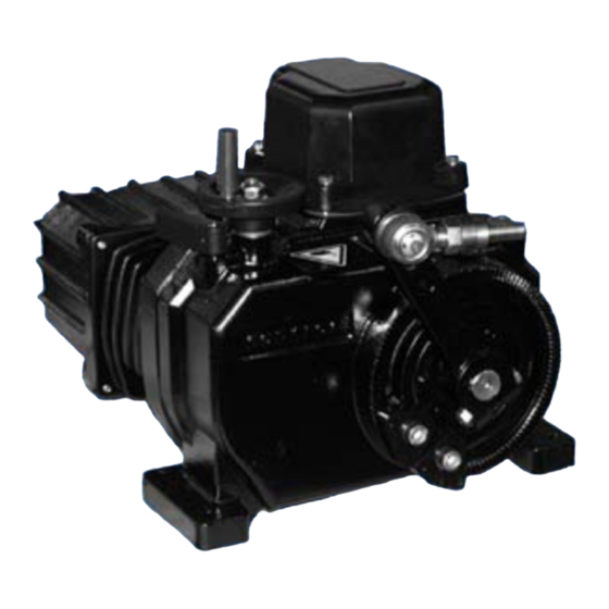
ABB Contrac PME120AI Instrukcja obsługi - Strona 6
Przeglądaj online lub pobierz pdf Instrukcja obsługi dla Kontroler ABB Contrac PME120AI. ABB Contrac PME120AI 18 stron. Electrical part-turn actuator
Również dla ABB Contrac PME120AI: Instrukcja obsługi (20 strony)

8.4 Mounting the Actuator to the Valve
8.4.1 Preparing the Equipment
- Make sure that the shaft and lever bore surface are clean and free of grease.
- Determine the length of the stay tube (not included in the scope of delivery).
- Move the valve to the "CLOSED" position.
- Move the actuator to the corresponding end position using the handwheel. Observe the permissible
angle.
- Spacing "L" minus 140 mm yields the required length of the link tube.
- Drill a cone bore into the valve lever for mounting the second ball-and-socket joint, as shown in
Figure 4.
- Insert the ball-and-socket joint, secure with crown nut and split-pin.
- Remove the welding bushings and weld them to the stay tube (C 15 to DIN 17210)
- Insert the link rod between the two ball-and-socket joints and screw it in.
- If required adjust "L" by turning the link rod.
- When all adjustment steps are finished, fasten the counter nuts.
8.4.2 Adjusting the Stops in Dependence of the Travel
- Move the output lever / valve to the position requiring fine adjustment.
- Put the stop onto the toothing as close to the output lever as possible and fasten with screws.
- Move the output lever towards the stop using the handwheel; turn the coupling rod for fine adjust-
ment.
- Fasten the counter nuts.
- Fasten the stop in the other mounting position close to the end position, depending on the toothing.
8.4.3 Adjusting the Stops in Dependence of the Torque
- First proceed as described above for travel-dependent adjustment.
- Prior to re-fastening the counter-nut lock the handwheel and then turn the coupling rod in such a
way that an initial tension occurs in the valve's closing position.
- Fasten the counter-nuts.
rigid, vibration-free
support
Fig. 2: Mounting PME 120, example
α ≥ 15 °
β
according to dimensions specified by the valve manufacturer
6
tightening torque
for limit stop screws: 46 Nm
echanical
limit stop
coupling
flap
lever
α
tightening torque for
lever clamping screw:
β
23 Nm
lever
boring diameter for
fastening screws: 12 mm
tensile strength:
≥ 400 Nm
°
3
°
10
r00304e1
