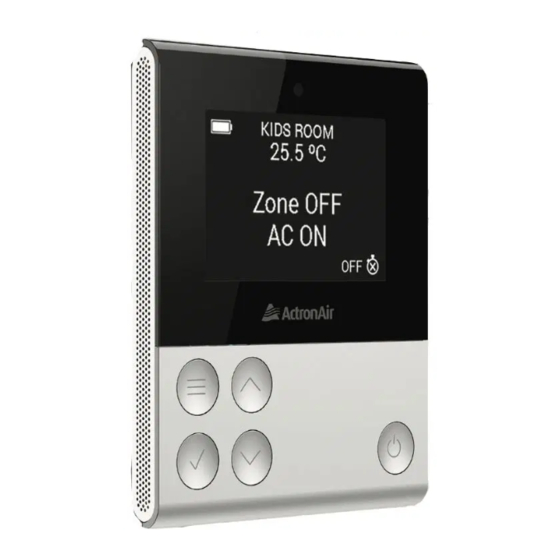
ActronAir QUE QZW-100 Instrukcja instalacji i obsługi - Strona 3
Przeglądaj online lub pobierz pdf Instrukcja instalacji i obsługi dla Kontroler ActronAir QUE QZW-100. ActronAir QUE QZW-100 13 stron.
Również dla ActronAir QUE QZW-100: Instrukcja instalacji i obsługi (13 strony)

Zone Control / Remote Sensor Installation
Location
•
ENSURE that the zone device (zone controller or remote sensor) distance
from wall controller (master or secondary) is within the recommended
RF range of 30m.
•
Do not install the zone devices on external walls, directly below the supply air
grille or near other additional heat load sources, as these locations may alter
sensor readings.
•
Do not install zone devices near magnetic, metallic objects or install near
power cables as these may effect the RF performance.
•
Avoid looping a longer cable as this may emit an electric noise.
•
Ensure there is ample space (25cm) around the zone device to ensure proper
air temperature reading and adequate access for removal.
•
It is recommended to use the included wall mates to hold mounting screws.
•
In the event a defective device is replaced, remember to pair the new one
to the master wall controller.
•
Use a maximum of 20m Cat5E cable.
•
Plug the power cable into its designated zone damper terminal
or zone module terminal (using 3-way cable joiner).
•
DO NOT use battery and zone power cable at the same time.
•
Make sure that the zone devices are installed in an upright position.
4
Dining
Power Supply Options (applicable for both zone controller and remote sensor)
24.0 C
o
Zone OFF
AC OFF
OFF
a
Dining
24.0 C
o
Dining
24.0 C
o
Zone OFF
Zone OFF
AC OFF
AC OFF
OFF
OFF
Dining
24.0 C
o
Zone OFF
AC OFF
b
OFF
i) via damper motor option
approx. 1.5m
from the ground
ii) or via 8Z-Module
AAA Battery Supply
+
AAA
1.5V
AAA
AAA
1.5V
AAA
+
AAA
1.5V
AAA
AAA
1.5V
AAA
4 x AAA - Zone Controller
2 x AAA - Remote Sensor
12VDC using Cat5E cable (Green Cat5E spec cables with RJ45 connectors & cable boots)
Maximum 20m from the
1.5V
AAA
nearest power junction.
1.5V
AAA
1.5V
AAA
1.5V
AAA
1.5V
AAA
1.5V
AAA
Maximum 20m from the
nearest power junction.
1.5V
AAA
1.5V
AAA
1.5V
AAA
To damper motor
1.5V
AAA
1.5V
AAA
1.5V
AAA
-
-
NOTE:
Do not use a battery and 12VDC power supply at the
same time. This type of set up could damage the
controller. Prolonged usage of battery may result in
leakage and will eventually damage the PCB.
5
