ASL INTERCOM PS 19 A Manual do utilizador - Página 4
Procurar online ou descarregar pdf Manual do utilizador para Sistema de intercomunicação ASL INTERCOM PS 19 A. ASL INTERCOM PS 19 A 9 páginas. Single channel beltpack with pgm (aux) input
4.0
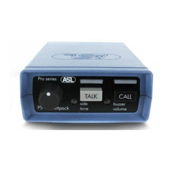
FRONT PANEL CONTROLS
1
PGM VOLUME control knob
This knob is for adjusting the listen level of the
PGM input signal.
2
VOLUME control knob
This knob is for adjusting the listen level of the
intercom signal.
3
TALK button
By pushing this button the signal of the headset
microphone is sent to the intercom party line.
When the TALK button is switched On, its large
green LED is lit.
Momentary switching:
When the TALK button is pushed and held, the
microphone signal is sent to the intercom channel
until the button is released.
5.0
REAR PANEL CONNECTORS
5
PGM connector
This XLR-3 connector is for feeding PGM signals
into the PS 19A. The input is electronically
balanced and accepts audio levels between -18
dBu and +22 dBu when configured for line level
or between -38 dBu and +2 dBu when configured
for mic. level.
See also section 'Internal Controls'.
Pin assignment:
pin 1: 0V /ground
pin 2: signal +
pin 3: signal -
6
LINE connector
This XLR-3 connector is for connecting the PS
19A to the intercom party line.
Pin assignment:
Pin 1: 0V / ground shield
Pin 2: +30V DC power wire
Pin 3: audio wire
PAGE 3
User Manual PS 19A / Issue 2011 © ASL Intercom BV
Latched switching:
When the TALK button is pushed shortly it is
electronically latched and the microphone signal
is sent to the intercom channel. When pushed
again, the TALK button switches Off.
Mic Mute when latched On:
After a so-called Mic Mute signal has been
received from a Pro Series master station or
power supply, the connection between
microphone and intercom channel is interrupted.
By pushing the TALK button, the connection is
restored and one can talk to the intercom channel
again.
4
CALL button
With a momentary push of the CALL button, a
Call signal is sent to all stations connected to the
intercom party line. The Call LED's of this
beltpack and of all stations on the party line start
flashing. By pushing the Call button for 2 seconds
the Call Buzzers are activated, provided the
buzzers are not muted by a Buzzer Mute signal
received from a Pro Series master station or
power supply. After the CALL button is released
the LED's continue to flash for a further 2
seconds
7
HEADSET connector
This XLR-4 connector is for connecting a headset
to the beltpack. The impedance of the headset
can must be minimum 200 ohms; in case the
headset has 2 cans in parallel, the impedance of
each can must be minimum 400 ohms.
Pin assignment:
Pin 1: shield mic. (GND)
Pin 2: mic. +
Pin 3: phones +
Pin 4: phones –