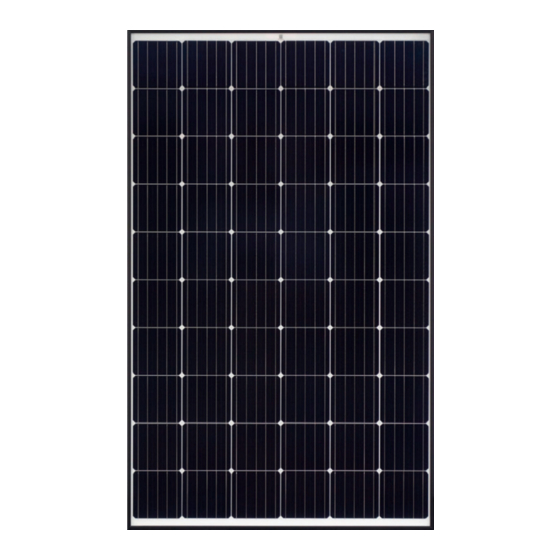
Astronergy CHSM6610MBL Manual de instalação - Página 5
Procurar online ou descarregar pdf Manual de instalação para Equipamento industrial Astronergy CHSM6610MBL. Astronergy CHSM6610MBL 12 páginas. Crystalline silicon pv
Também para Astronergy CHSM6610MBL: Manual de instalação (18 páginas), Manual de instalação (19 páginas), Manual (19 páginas)

2.2.7 Do not unplug the connector under load.
2.2.8 Do not work alone.
2.2.9 Wear a safety belt if working far above the ground.
2.2.10 Do not wear metallic jewelry, which can cause electric shock, while installing or
troubleshooting the PV system.
2.2.11 Follow the safety regulations for any and all other system components, including wires,
connectors, charging regulators, batteries, inverters, etc.
2.2.12 Do not expose wires to direct sunlight. Use UV-resistant cable.
2.2.13 Do not damage the surrounding PV modules or mounting structure when replacing a PV
module.
2.2.14 Do not change any PV module components (diode, junction box, plug connectors, etc.).
2.2.15 Maximum reverse current is 20.25A for module with 6 inch cells. Application of the
blocking diode and fuse in the combiner box are recommended for reverse current
protection when more than two strings are connected in parallel.
2.2.16 A certain gap is maintained between the PV module and the mounting surface to prevent
the mounting surface touching the junction box.
2.2.17 Standing on the solar PV module is forbidden and also prohibit installation tools or other
objects hitting surface of the solar PV module.
2.2.18 The solar modules are recommended to be installed over a fireproof and insulating roof
covering when installed on a roof.
2.2.19 PV cable connection cannot be too tight, it is recommended that the connector and the
backsheet have a certain gap.
2.2.20 Region for sand blown, in order to avoid the sand into the connector, we suggest to short
circuit module connectors before installation; If into the grains of sand, may cause internal
live parts wear and tear, so there are some electrical safety hidden trouble.
3
Mechanical Installation
3.1 Installation Conditions
3.1.1 Extreme environment temperature -40
3.1.2 Operating temperature -40
3.1.3 Mechanical load on panels (e.g., snow/wind): The max tested snow/wind load is
6000Pa/3600Pa, and the design load is 4000Pa/2400Pa with a safety factor 1.5 under
standard mounting system. Please refer to the detailed mounting instructions as Chapter
3.2.
3.1.4 Tilt Angle selection: The installation should be facing north in the southern hemisphere
and facing south in the northern hemisphere.
3.1.5
to +85
to +85
the fire class of the roof and building
