Air King 5000 Manual de instalação e operação - Página 3
Procurar online ou descarregar pdf Manual de instalação e operação para Humedecer Air King 5000. Air King 5000 12 páginas. Flow-through furnace humidifier
Também para Air King 5000: Manual de garantia, manutenção e resolução de problemas (14 páginas), Manual de resolução de problemas (13 páginas)
• READ THESE INSTRUCTIONS FULLY BEFORE INSTALLING
THIS HUMIDIFIER.
• SAVE THESE INSTRUCTIONS FOR REFERENCE.
• WHEN DRILLING OR CUTTING INTO DUCTING BE
EXTREMELY
CAREFUL
CONDITIONING COILS OR OTHER FURNACE APPARATUS.
• THIS UNIT MUST BE INSTALLED ON 10" WIDE DUCTING
MINIMUM.
• FOR THIS UNIT TO OPERATE PROPERLY YOUR FURNACE
SHOULD ACHIEVE A HEATING TEMPERATURE OF AT LEAST
35°C IN ONE MINUTE. IF IT DOES NOT YOU MAY HAVE TO
PURCHASE A PRESSURE ACTIVATION SWITCH (SOLD
SEPARATELY)
• DO NOT INSTALL THIS UNIT WHERE EXTREME
TEMPERATURES EXIST (BELOW 45°F – ABOVE 145°F).
• THIS UNIT REQUIRES A DRAIN TO ALLOW WATER TO
FREELY RUN OFF.
• FOR THIS UNIT TO OPERATE PROPERLY IT MUST BE
INSTALLED ON A FORCED AIR HEATING SYSTEM WITH A
SUPPLY DUCT and A RETURN DUCT.
• THE HUMIDIFIER BODY and THE BYPASS COLLAR DAMPER
ARE TO BE INSTALLED ON DUCTING ONLY. UNDER NO
CIRCUMSTANCES MOUNT EITHER COMPONENT TO THE
FURNACE BODY.
• ELECTRICAL WIRING, WATER SUPPLY and DRAIN TUBE
MUST NOT KINK OR COME INTO CONTACT WITH SHARP
EDGES OR HOT SURFACES.
• IF REPLACING AN EXISTING FURNACE HUMIDIFIER, WE
RECOMMEND YOU REPLACE ALL COMPONENTS TO
ENSURE PROPER HUMIDIFIER OPERATION.
• THE INSTALLATION OF THIS PRODUCT MUST COMPLY
WITH NATIONAL AND LOCAL ELECTRICAL, PLUMBING,
BUILDING, AND MECHANICAL CODES.
REQUIRED TOOLS
• Safety glasses
• Work gloves
• Electric drill
• Drill bits (3/8", 1/8", 5/64")
• Tin snips
• Full size Philips or Roberstons screw driver
• Short handle Philips or Roberstons screw driver
• Adjustable wrench
• Utility knife
• Pliers
• Level
INSTALLATION AND OPERATING INSTRUCTIONS:
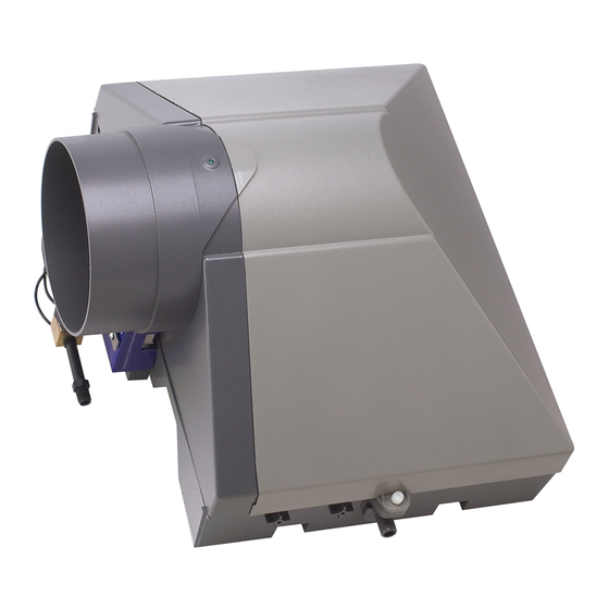
MODEL 5000 FLOW THROUGH HUMIDIFIER
NOT
TO
DAMAGE
Model 5000 Flow Through Humidifier
• Measuring tape or ruler
• Medium-grit sand paper
• Pencil
• Tape
AIR-
SELECTION OF LOCATION
TO MOUNT THE HUMIDIFIER
All bypass type furnace humidifiers rely on the pressure
difference which exists between the supply duct (hot air) and the
return duct (cold air) to create and air-flow through the
humidifier's evaporator pad. The air will ALWAYS flow from HOT
(high pressure) to COLD (low pressure).
Selecting the proper location, and installing the humidifier
properly as intended by the manufacturer is imperative for the
proper operation of the humidifier – see illustrations below along
with the brief explanations as to what is a good installation and
what is not.
• INSTALLATION TIP: Before starting fully plan out the
installation. Check for the locations of the humidifier,
bypass collar and damper, the length and type of ducting
required, the water supply, the water drain, the electrical
wiring, and a constant 120 volt outlet to plug in the
transformer. This will ensure your installation goes as
easy and quickly as possible.
IDEAL INSTALLATION
Figure 1
SUPPLY DUCT
WARM AIR
Damper fully open
1. The humidifier body and bypass tube are installed at eye level,
easily accessible for installation and routine maintenance.
2. The space between the humidifier body and bypass tube are no
more than 30" to ensure maximum air flow through the humidifier.
3. The aluminum flex bypass tube are cut to the proper length
and pulled tight to ensure maximum air flow.
RETURN DUCT
COLD AIR
10" wide duct minimum
No more
than 30"
Bypass collar and
unit level
Bypass tube pulled
tight and cut to length
Water flowing to drain
3