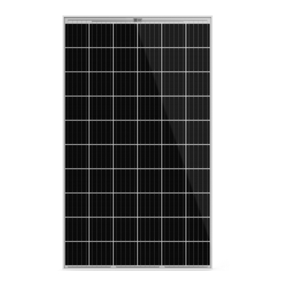
Aleo X63 Manual de instalação - Página 8
Procurar online ou descarregar pdf Manual de instalação para Unidade de controlo Aleo X63. Aleo X63 20 páginas.
Também para Aleo X63: Manual de instalação (20 páginas)

8
Mechanical installation
8.1 Mounting orientation of modules
8.1.1
Vertical (portrait) mounting
When mounting the module vertically, make sure that the cables
are facing towards the ground and the junction box is facing up-
wards.
8.1.2
Horizontal (landscape) mounting
When mounting horizontally, make sure that the exit holes for the
cables on the module or the junction box are positioned on the
inside of the photovoltaic generator (see fig. 1). Avoid the lateral
outer edges of the photovoltaic generator to minimise the effect of
ambient conditions, such as wind or rain.
Fig. 1
Recommended position of the junction boxes for horizon-
tal mounting (facing the middle of the generator).
8.1.3
Inclination
Incline the surface of the modules at an angle of at least 10° hori-
zontally, so that precipitation can drain off which supports the
modules self-cleaning. For optimum self-cleaning, aleo recom-
mends an angle of at least 15° horizontally.
In case of flat installation, we recommend the use of our frameless
module.
8.2 Safety precautions
S
Do not drill any additional hole in the frame of aleo modules.
8.3 Improper mounting
#
Do not attach the modules using nails. The vibration created in
the process can cause micro fissures and loss of yield, and re-
sults in loss of warranty rights.
Do not attach the modules by welding. The temperatures cre-
ated in the process can cause delamination, micro fissures and
loss of yield, and results in loss of warranty rights.
aleo solar GmbH | Marius-Eriksen-Straße 1 | 17291 Prenzlau | Germany |
8.4 Intervals
8.4.1 Intervals between modules with standard frame
Leave a minimum clearance when mounting modules. This
prevents mechanical tension due to thermal expansion.
When mounting at intervals, leave a clearance of 5 mm or more
between the individual module frames.
For edge-to-edge mounting, allow for an expansion joint of
30 mm after a maximum of 7 m.
The recommended maximum clearance is 30 cm, based on the
modules standard cable length.
aleo solar recommends mounting at intervals. Also note the infor-
mation from the mounting equipment vendor. This could specify
larger intervals.
8.4.2
Rooftop or freefield mounting
Roof integrated mounting
The largest permissible clearance is defined by national stand-
ards. This is used to design the installation on the assumed ef-
fects of wind and suction.
The actual maximum clearance of an installation is determined
by the sub-structure. Ensure that your sub-structure adheres to
the permissible clearances.
EIS#
Clearance under the modules
Minimum clearance
Ensure a clearance of at least 4 cm between the rear
edge of the frame and the mounting surface (e.g. the roof
tiles) for the rear ventilation of the aleo module.
Ensure an appropriate interval, for example, to the
trough of the mounting system. Also ensure adequate
ridge ventilation, for example, with a roof ridge ventila-
tor.
Maximum clearance
Installation manual Ver. 4.8, 05/2021, en
Page 8 of 20
