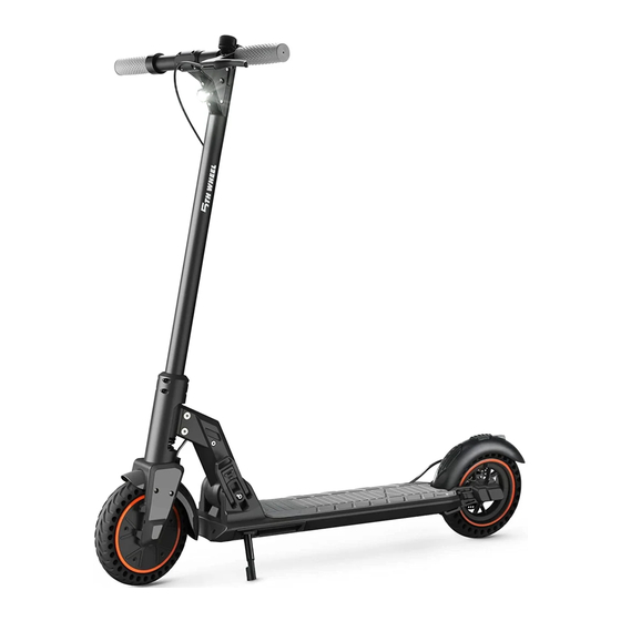
5th Wheel 5LCHM02 Manual do utilizador - Página 12
Procurar online ou descarregar pdf Manual do utilizador para Scooter 5th Wheel 5LCHM02. 5th Wheel 5LCHM02 18 páginas.

8 Indication Description
LED Power Indication
Each LED indicator represents 20% of power. When the battery power is below 10%, M5 flashes.
>80%
>60%
M1-M5 light up
M3-M5 light up
Cruise Control Indication
Turn On
When the cruise control is turned on, the indicator light
will stay on.
T3 lights up
Headlight Indication
Turn On
When the headlight is turned on, the indicator light will
stay on.
T1 lights up
Gear Indication
Gear 1
Gear 1 is enabled.
T6 lights up, T7 & T8 go out
T7 lights up, T6 & T8 go out
20
>40%
>20%
M4-M5 light up
M5 light up
Turn Off
When the cruise control is turned off, the indicator light
goes out.
T3 goes out
Turn Off
When the headlight is turned off, the indicator light goes
out.
T1 goes out
Gear 2
Gear 3
Gear 2 is enabled.
Gear 3 is enabled.
T8 lights up, T6 & T7 go out
Error Indication
If there is anything abnormal about the scooter, the warning indicator will flash, with the flashing
<10%
value E1-E6 displayed.
M5 flashes
Errors
Code
Communication
Fault
Brake failure
Throttle Failure
Motor Fault
Controller failure
Overheated Motor
Over-speed alert
Flashing
Solutions
Please check whether the taillight is on. If it is off, it means that the power supply is insufficient.
E1
Please replace the controller or the LED display. If it is on, please check whether the connecting
wire between the controller and the LED display is open-circuit.
Press and release the brake to reset the brake.
f not, please check whether the
E2
Please check whether the
connecting wire between the
brake is pressed.
brake and the LED display is
short-circuited or open-circuit.
Press and release the throttle to reset the throttle.
If not, please check whether the
Please check whether the
E3
connecting wire between the
throttle is pressed.
throttle and the LED display is
short-circuited or open-circuit.
If it is not connected correctly, please adjust and connect the motor and the
controller correctly.
If it is connected correctly, please disconnect the connecting wire
E4
Check whether the motor
and measure whether the internal resistance between the
and controller wire is
three-phase wires of the motor is within a reasonable range,
connected correctly.
generally within 0.1Ω-1Ω. If it exceeds the range, the motor needs
to be replaced.
E5
If the controller is damaged, please replace the controller.
If the motor temperature is too high, please wait for the motor to
cool to the appropriate working temperature.
Check whether the motor
E6
If the motor temperature is normal, check whether the connecting
temperature is too high.
wire of the controller is short-circuited. If it is short-circuited,
please replace the connecting wire.
Reduce the riding speed.
If it is open-circuit or short-
circuited, please replace the
connecting wire.
Replace the brake handle.
If it is open-circuit or short-
circuited, replace the connecting
wire.
Replace the throttle.
21
