Gage Bilt GB568 Manual de instruções original - Página 12
Procurar online ou descarregar pdf Manual de instruções original para Ferramentas de rebitar Gage Bilt GB568. Gage Bilt GB568 20 páginas. Installation tool
Também para Gage Bilt GB568: Manual de instruções original (16 páginas)
Providing all maintenance conditions have been met, follow this systematic approach to diagnosis.
1. NO OPERATION WHEN ACTUATOR ASSEMBLY-AIR (704130) IS DEPRESSED.
a.) Air connection may be loose or damaged.
b.) Faulty Actuator. Replace.
c.) Check hydraulic fittings; tighten, repair or replace.
2. SLOW OR PARTIAL OPERATION WHEN ACTUATOR ASSEMBLY-AIR (704130) IS DEPRESSED.
a)
Back-up ring (401094) or o'ring (A-262) on the head piston (568109) could be worn or damaged. Replace.
b)
O'rings (A-914) and back-up ring (731134) on piston rod assembly (722133) could be worn or damaged. Replace.
c)
Muffler (704146) or filter inside valve spool assembly (703142) may be plugged with dirt. Clean thoroughly and back-blow
with compressed air.
d)
Hole in metering screw in valve spool assembly (703142) may be blocked or damaged. Hole diameter should be .028" (.71 mm).
Clear and size or replace.
e)
Excessive wear or scoring on moving parts. Check and replace faulty parts.
3. TOOL OPERATES IN REVERSE.
a.) Check that tool is properly connected to pull side of power source.
4. NO OPERATION WHEN ACTUATOR ASSEMBLY-AIR (704130) IS DEPRESSED.
a)
Tool seized due to mechanical failure or damaged parts.
5. OIL LEAKAGE.
a)
DO NOT
OPERATE WITH OIL LEAKING FROM TOOL. HIGH PRESSURE OIL MAY CAUSE SEVERE PERSONAL INJURY.
b)
Oil leaks from tool. Determine source of leak and replace worn or defective o'rings and back-up rings.
6. AIR BYPASS FROM VALVE HOUSING.
a)
If the spring (704141) breaks or dislodges, air will flow freely through the muffler (704146). Replace or reset. Valve spring
installation tool assembly (704262) is recommended.
b)
Check o'rings on valve sleeve (703139), valve spool assembly (703142), and valve plug (704145). If worn or damaged,
replace. Valve sleeve removal tool assembly (704163) is recommended.
7. COLLAR OF HUCKRIMP® FASTENER NOT SWAGED COMPLETELY.
a)
Tool operating improperly (see above troubleshooting).
b)
Scored anvil.
c)
Improper stroke. (See setting stroke below).
8. TOOL "HANGS UP" ON SWAGED COLLAR OF HUCKRIMP FASTENER.
a.) Tool operating improperly (see above troubleshooting).
b.) Check that tool is returning properly. Spring (568105) may be worn. Replace
WARNING:
Never actuate/dry cycle the tool with nose assembly attached unless a fastener is positioned in the nose assembly.
WARNING:
Incorrect stroke will damage the nose assembly.
Note: The tool stroke is factory set at .100" (2.54 mm).
Recommended stroke point for 5/32", 3/16" and 1/4" is .100" (2.5 mm).
When adjusting stroke remove nose assembly.
To adjust stroke: (See
WARNINGS
1.
Adjust the stroke based on fastener size and manufacturers
crimp specifications.
2.
Loosen the set screw (75315).
3.
Then turn the set screw (405001) clockwise to decrease the
stroke and counter clockwise to increase the stroke.
4.
After desired stroke is set, tighten set screw (75315) to lock.
5.
Check crimped fastener with GO/NOGO gage to determine
if a fine adjustment is required.
6.
Fine adjustments should be done by 1/8 to 1/4 turns until
desired diameter is achieved.
To set stroke: (See
WARNINGS
1.
Using a pair of dial calipers, measure "A" dimension.
2.
Holding in actuator, measure "B" dimension.
3.
Subtracting "A" dimension from "B" dimension equals stroke.
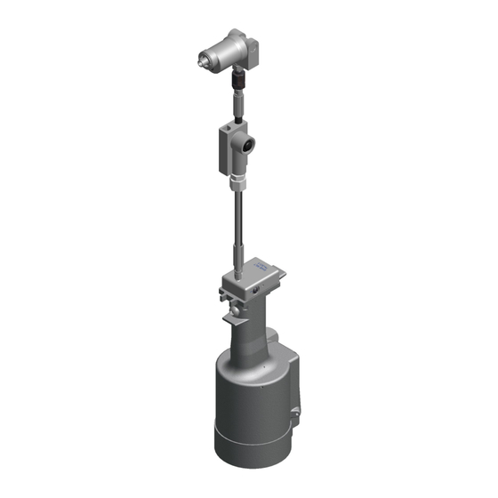
GB722/568 INSTALATION TOOL
TROUBLESHOOTING
SETTING AND ADJUSTING STROKE
above).
above).
12
SET SCREW
405001
SET SCREW
75315
11/21 REV. 5/22