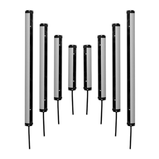
Autonics BW20-24 Manual do produto - Página 2
Procurar online ou descarregar pdf Manual do produto para Acessórios Autonics BW20-24. Autonics BW20-24 4 páginas. Single-beam area sensors
Também para Autonics BW20-24: Manual (6 páginas)

Cautions during Installation
• Be sure to install this product by following the usage environment, location, and
specified ratings. Consider the listed conditions below.
- Installation environment and background (reflected light)
- Sensing distance and sensing target
- Direction of target's movement
- Feature data
• If the installation environment has reflected light from the wall or floor, a interval
distance of at least 0.5 m is required.
• When installing multiple sensors closely, it may result in malfunction due to mutual
interference. Install it by referring to the interference protection and the installation
method in the manual.
• Do not use in places where the light-receiving sensor is exposed to direct sunlight or
where the ambient illumination is higher than the specification.
• Do not impact with a hard object or bend the cable excessively. That could decrease
the product's water resistance.
• Use this product after the test. Check whether the indicator works appropriately for
the positions of the detectable object.
Ordering Information
This is only for reference, the actual product does not support all combinations.
For selecting the specified model, follow the Autonics website.
BW
❶
-
❷
❸
❶ Optical axis pitch
Number: Optical axis pitch (unit: mm)
❸ Control output
No-mark: NPN open collector output
P: PNP open collector output
Product Components
• Product × 1
• Instruction manual × 1
Sold Separately
• Connection cable: CID4-□T(R) (1 set - emitter and receiver)
Connections
Brown
12 - 24 VDCᜡ
White
Blue
0 V
Black
■ NPN open collector output
Brown
1
+
White
2
-
Black
4
Blue
3
Brown
1
White
2
Black
4
LOAD
OCP
SCP
Blue
3
• OCP (over current protection), SCP (short circuit protection)
Operation Timing Chart
❷ Number of optical axes
Number: Number of optical axes
• Bracket A × 4
• Bracket B × 4
• Fixing bolt × 8
SYNC
TEST (M/S) (emitter) / OUT (receiver)
■ PNP open collector output
Brown
1
White
2
Black
4
Blue
3
Brown
1
OCP
SCP
White
2
Black
4
LOAD
Blue
3
ON Level
Stable light ON area
OFF Level
Unstable light ON area
Unstable light OFF area
Stable light OFF area
ON
ON LED
OFF
(green)
ON
UNSTABLE LED
OFF
(yellow)
ON
OFF LED
OFF
(red)
ON
Control output
OFF
(Light ON)
Dimensions
• Unit:mm,Forthedetaileddrawings,followtheAutonicswebsite.
Emitter
Optical axis
■ Optical axis Pitch (A, B)
20 mm
Product
Model
length
(L)
BW20-08(P)
160
BW20-12(P)
240
BW20-16(P)
320
BW20-20(P)
400
BW20-24(P)
480
BW20-28(P)
560
BW20-32(P)
640
BW20-36(P)
720
BW20-40(P)
800
BW20-44(P)
880
BW20-48(P)
960
■ Bracket A
2-R1.7
26.6
2-4.4
16
Operation Indicator
+
-
ON
◑
●
OFF
◑◑ / ◑◑◑
01) R epeated twice, flashes twice at 0.5 second intervals
Item
Power ON
MASTER operation
SLAVE operation
TEST input
Break of emitter
Break of light emitting
element
Normal installation
Hysterisis section
Abnormal
installation
Stable light ON
Unstable light ON
Unstable light OFF
Stable light OFF
Break of receiver
Over current
Synchronous line noise
Receiver
Emitter failure (Time out) -
Optical axis
misalignment alarm
28.6
28.6
Operation
indicator
Ø 5
M12
■ Optical axis Pitch (A, B)
40 mm
Num. of
Sensing
optical
Model
height
axes
8
140 mm
BW40-04(P)
12
220 mm
BW40-06(P)
16
300 mm
BW40-08(P)
20
380 mm
BW40-10(P)
24
460 mm
BW40-12(P)
28
540 mm
BW40-14(P)
32
620 mm
BW40-16(P)
36
700 mm
BW40-18(P)
40
780 mm
BW40-20(P)
44
860 mm
BW40-22(P)
48
940 mm
BW40-24(P)
■ Bracket B
50 °
Ø 20
2-R1.7
Ø 20
18
Flashing at 0.5 sec interval
01)
Flashing simultaneously at
0.5 sec interval
Emitter
Receiver indicator
indicator
Green
Red
Green
Yellow Red
●
-
-
●
-
-
-
-
◑
-
-
-
-
●
◑
●
●
◑
●
●
◑
●
●
-
-
●
-
-
-
-
●
-
-
●
●
-
-
●
-
-
-
-
◑
●
-
◑
◑
-
-
Receiver
Product
Num. of
Sensing
length
optical
height
(L)
axes
160
4
120 mm
240
6
200 mm
320
8
280 mm
400
10
360 mm
480
12
440 mm
560
14
520 mm
640
16
600 mm
720
18
680 mm
800
20
760 mm
880
22
840 mm
960
24
920 mm
2-4.4
10
Cross-flashing at 0.5 sec
interval
Sequence flashing at 0.5
sec interval
Control
output
(Light ON)
-
-
-
-
-
-
-
-
-
-
OFF
◑
OFF
◑
OFF
◑
OFF
●
ON
●
ON
OFF
OFF
OFF
OFF
◑
OFF
◑
OFF
-
