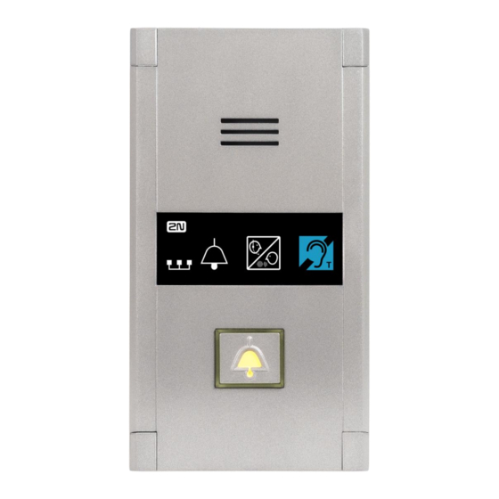
2N Lift1 Compact Breve manual - Página 5
Procurar online ou descarregar pdf Breve manual para Sistema de intercomunicação 2N Lift1 Compact. 2N Lift1 Compact 12 páginas. For lifts
Também para 2N Lift1 Compact: Breve manual (12 páginas)

connector
Short-circuit
connector used
WITH
VOICE AS
Interconnection
with Voice Alarm
Station switch
jumper
recovery mode
RECOVERY
MODE
PROGRAMMING
for 2N®
CONNECTOR
Programming Tool
12 V (24 V)
DC voltage
Note
Use 12–24 V DC of any polarity for voltage control. However, make sure that the source is
backed up against power outage. You can also connect a buzzer or horn in parallel with the
ALARM terminal if voltage control is used.
You can also use the NO contact or voltage presence for Alarm 1 and Cancel activation and
invert the function using parameters 920 or 916 if necessary – NC contact or voltage
absence for activation. The logic of the Alarm 1 functionality can be set automatically when
the device is first time switched on, the input has to be in not active alarm state.
Make sure that the DoorOpen signal is only activated when both the internal and
external lift doors are open and the people can leave the cabin safely.
Telephone Line Connection
Lift1 works regardless of polarity and/or line parameters in a wide range (see the Technical
Parameters section). It is connected via the LINE terminals. A great advantage is that Lift1
requires no additional power supply for operation. For details on Lift1 connection to PSTN, PBX
and GSM gateway lines refer to the Lift1 Connecting Options section.
Mounting completion
Having connected the wires, you can complete the Lift1 wall mounting. If you can access the
cabin wall from the outside, use the mounting type that prevents dismantling and unauthorised
tampering from the cabin. Mounting procedure:
Where access from the outside is possible, use the four pre-drilled M4 holes in the corners.
Remove the corner covers fitted with four M4 screws from behind.
Screw the 30 mm long M4 headless grub screws included in the audio unit package in
place of the corner cover screws removed. Tighten the screws with an internal hexagon
key wrench.
Put the audio unit on the holes, apply the serrated lock washers from the outside and
screw the M4 nuts (both included in the delivery).
This type of mounting is suitable for lift cabin wall thickness of up to 20 mm.
Standard functionality of
Lift1
Used for connection of
audio units under and
above the lift cabin
Set the jumper to ON to activate the recovery mode
for FW upgrade whenever a problem occurs with the
®
Lift1 – 2N
Service Tool connection.
USB programming tool for
®
2N
Service Tool via PC
After power connection is backlighted the Alarm
button. If the rescue feature is activated, then the
yellow LED is shining.
®
2N
Voice Alarm
Station connector
configuration,
firmware, voice menu
4
