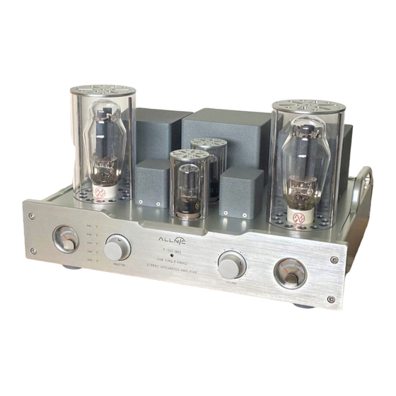
ALLNIC AUDIO T-1500 MK2 Manual do Proprietário - Página 7
Procurar online ou descarregar pdf Manual do Proprietário para Amplificador ALLNIC AUDIO T-1500 MK2. ALLNIC AUDIO T-1500 MK2 13 páginas. 300b set stereo integrated amplifier

DO consider using a high quality power cord, interconnects and speaker cables. The T-1500
•
MK2 is a highly sensitive piece of electronic designed for neutrality and will output what you
put into it. Allnic's Zero Loss Technology cables will work synergistically with the T-1500 MK2.
DO try to place T-1500 MK2 away from major sources and potential receivers of RFI and EMI.
•
Though well shielded, the T-1500 MK2 will function best away from large power transformers
and other sources of such interference and from other equipment that could be susceptible to
such forms of interference.
INPUTS
B.
There are four (4) RCA type female inputs (See Figure 5). Your interconnects will require male RCA
terminations. Facing the rear of the chassis, the input connections are to the right of the IEC power input
and the Pre Out terminal pair. The left channel connector is the top one in each line input pair.
PRE OUT CONNECTIONS
C.
The T-1500 has a pair of RCA type female Pre Out (Preamplifier outputs) connections on the rear of the
chassis, between the IEC connection and the Line Inputs (See Figure 5). The Pre Outs are connected
passively; therefore, when they are in use, the 6SL7, 6SN7 and 300Bs continue to draw power and
operate. These connections are for use to connect to one or a pair of powered subwoofers or, for bi-
amping, to an external stereo power amplifier or pair of monoblock amplifiers (preferably with the
same gain as the T-1500 MK2).
SPEAKER TERMINALS
D.
The T-1500 MK2 is equipped with two pairs of high-quality speaker terminals. These terminals are
located at the left of the back of the chassis (the right, facing the front of the chassis – See Figure 5).
The positive terminal for each pair is on top, the negative below. Between the pairs of terminals is a
vertically oriented toggle switch to select between either 4 or 8 ohm speaker impedance or 8 and 16
ohm impedance, as pre- specified by the owner. The T-1500 MK2 utilizes a circuit design that provides
for full power from the output transformer regardless of the impedance selected with the toggle
switch. Set the toggle switches to your preferred speaker impedance. Facing the rear of the chassis, the
right pair are on the left outside left and the left channel pair are on the inside right. Facing the front of
the chassis, the right channel pair is on the outside right and the left channel pair is to their left, on the
other side of the impedance toggle. The terminals accept bare wire (not recommended) and spade and
banana type connectors.
POWER CONNECTION
E.
Connect the input interconnects and the speaker cables or the Pre Out connections before you insert
the power cable into the receptacle at the centre of the chassis rear. The T-1500 MK2 uses a standard
three prong male IEC connection for AC input (See Figure 5). You need to use a power cord with a
female three prong IEC connector at one end. The T-1500 MK2 you have purchased is set internally for
either for AC 110/120 volt – 60 HZ, or 220/230 volt – 50 Hz operation. There is no way to change this to
another AC setting without return of the unit to the factory for re-wiring, at the owner's cost, including
transport both directions.
7
