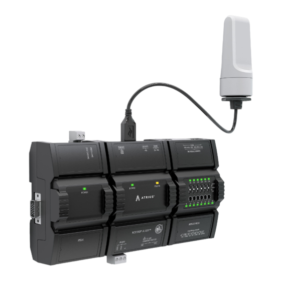
Acuity Controls ECLYPSE A1000 Manual de instalação - Página 3
Procurar online ou descarregar pdf Manual de instalação para Relés Acuity Controls ECLYPSE A1000. Acuity Controls ECLYPSE A1000 10 páginas. Asset tracking
Também para Acuity Controls ECLYPSE A1000: Manual de instalação (14 páginas)

1.0 - Introduction
1.1 Product Description
This document describes the installation procedures for
the ECLYPSE A1000AT. The ECLYPSE A1000AT
manages and controls a network of asset tags as part of
the Atrius Assets Solution. This programmable device
provides advanced functionality to process messages
from the asset tags and deliver them to the Atrius cloud.
For more detailed information about the ECLYPSE
A1000AT and its capabilities please refer to the
ECLYPSE A1000AT User Guide.
1.2 General Installation Requirements
For proper installation and subsequent operation of the
ECLYPSE A1000AT, pay special attention to the follo-
wing recommendations:
•
Upon unpacking the product, inspect the contents
of the carton for shipping damages. Do not install
damaged modules.
•
Avoid areas where corroding, deteriorating or explo-
sive vapors, fumes or gases may be present.
•
Ensure the mounting surface can support the cont-
roller, DIN rail, and optional enclosure.
•
Allow for proper clearance around the controller's
enclosure and wiring terminals to provide easy
access for hardware configuration and maintenance,
and to ventilate heat generated by the controller.
•
The controller's mounting orientation must be
horizontal with the controller's back attached to a
vertical wall surface. Orient the controller with the
ventilation slots and power supply input terminal
block connectors towards the top to permit proper
heat dissipation. When installed in a 3rd party enclo-
sure, select one that provides sufficient surface area
to dissipate the heat generated by the controller
and by any other devices installed in the enclosure.
A metal enclosure is preferred. If necessary, provide
active cooling for the enclosure.
•
The controller's datasheet specifies the power
consumption (amount of heat generated), the
operating temperature range, and other environ-
mental conditions the controller is designed to
operate under.
•
Ensure that all equipment is installed according to
local, regional, and national regulations.
•
If the controller is used and/or installed in a manner
not specified by Acuity, the functionality and the
protection provided by the controller may be
impaired.
Acuity Brands | One Lithonia Way Conyers, GA 30012 Phone: 800.535.2465 www.acuitycontrols.com © 2017-2019 Acuity Brands Lighting, Inc. All rights reserved. 03/29/19
Any type of modification to any Acuity product will void the product's
warranty.
Take reasonable precautions to prevent electrostatic discharges to the
controller when installing, servicing or operating the controller.
Discharge accumulated static electricity by touching one's hand to a well-
grounded object before working with the controller.
1.3 Device Markings (Symbols)
Certain markings (symbols) can be found on the control-
ler and are defined as follows:
Symbol
CE marking: the device conforms to the requirements of applicable
EC directives.
Double Insulation marking: These controllers are built using double
insulation.
Products must be disposed of at the end of their useful life
according to local regulations.
Read the Hardware Installation Guide for more information.
For indoor use only.
UL marking: conforms to the requirements of the UL certification.
FCC marking: This device complies with FCC rules part 15, subpart
B, class B.
Warning Symbol: Significant information required. Refer to the
Hardware Installation Guide.
HIGH VOLTAGE Symbol: Direct contact will cause electrical shock or
burn.
Alternating Current
Direct Current
Line
Neutral
Description
A1000AT_IG_10_EN
3 of 10
