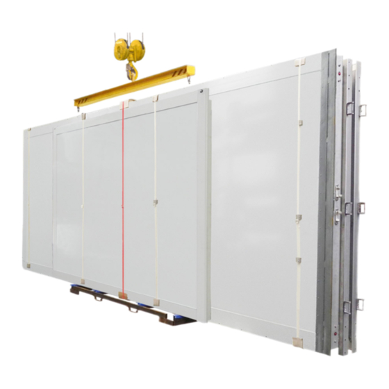
AluTeam BR 248-2 Manual de instruções de montagem - Página 7
Procurar online ou descarregar pdf Manual de instruções de montagem para Camiões AluTeam BR 248-2. AluTeam BR 248-2 12 páginas. Box body kits

1
MA 350081
LED strip, left
MA 350081
0.5-1
correct
wrong
Series 248-2 Assembly Instructions
2
LED strip, right
1
2
MA 350081
MA 350081
wrong
•
Now continue to connect the various lights:
To wire the LED strips
•
sor), fit together only
connection downwards into the left-hand frame pillar.
To wire the LED strips
•
only
1.
the connectors and push
downwards into the left-hand frame pillar.
Note:
The figure shows wiring with LED strips on the right
and/or on the left-hand side.
•
Fix the gusset plate in the corner pillars with 3 M 10 x 30 countersunk
screws MD100268 positioned on each side (tightening torque
60 Nm ± 5 Nm).
•
Screw the roof from the top using 3 - 4 screws on each side
MD100318 together with ring seals MD110044 uniformly distribut-
ed, each from the front to the back. Set the screwdriver tightening
torque to 5 Nm ± 1 Nm.
Attention:
To maintain the sealing function, the sealing washer
must not be pressed out from under the screw head by
more than approx. 0.5 - 1 mm!
•
Measure the diagonals of the frame and correct them if necessary,
until they match each other.
•
Screwing the remaining screws MD100224, M 6 x 21 mm Tx 30 to
a tightening torque of 10 Nm ± 1 Nm vertically into the side
walls-front wall connection, until the sections are pressed together.
•
Fill the remaining cavity between the front wall and side wall panel
with the piece of cut foam supplied.
•
Then close off the vertical front inside body corners with the corner
covers using the rivets MD150023.
•
Screw the remaining screws MD100318 with the ring seal MD110044
into the connection of the roof and walls. Again, pay attention to
deformation of the sealing washer (see above).
•
Tighten the screws MD100268 of the frame gusset plates at the top
as well as the screws M 12 x 45 mm, MD100307 of the frame cross
member to the required torque of 125 Nm ± 5 Nm.
Attention:
The rear surface of the two crossmembers must form a
flush plane with the rear surface of the pillars.
•
Now seal the component crossovers of the frame.
•
Remove the single-stud fittings from the roof assembly rails.
•
If necessary, screw the inside right handle onto the frame pillar.
•
Close off the side screw holes in the rear pillars using the plugs supplied.
Dated 11/2021
Previous instructions become invalid.
with
motion detectors (infrared sen-
1.
the connectors and push
without
motion detectors fit together
2.
the plug-in connection
2.
the plug-in
7 / 12
