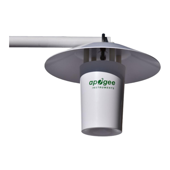
Apogee Instruments TS-120 Руководство пользователя - Страница 13
Просмотреть онлайн или скачать pdf Руководство пользователя для Нагреватель Apogee Instruments TS-120. Apogee Instruments TS-120 18 страниц. Fan-aspirated radiation shield

Conversion of Thermistor Resistance to Temperature
The thermistor is a resistive element, where resistance changes with temperature. Thermistor resistance (R
is measured with a half-bridge measurement, requiring a known excitation voltage input (V
of output voltage (V
):
OUT
V
EX
R
24900
T
V
OUT
where 24900 is the resistance of the bridge resistor in Ω. From resistance, temperature (T
with the Steinhart-Hart equation and thermistor specific coefficients:
T
K
A
B
ln(
R
T
-3
where A = 1.129241 x 10
, B = 2.341077 x 10
measured temperature in Kelvin can be converted to Celsius (T
T
T
273
.
15
C
K
Fan Operation
Under some environmental conditions (e.g., high wind speed, low solar radiation), accurate measurements can be
made without running the fan at full speed. Fan speed and power consumption can be decreased using a pulse
width modulation (PWM) signal. The PWM signal should have a frequency of approximately 20 kHz and a duty
cycle of 50 to 100 %, where a duty cycle of 100 % is full power and 50 % is low power. Running the fan in a low
power mode reduces the current draw from 80 mA to approximately 25 mA. The only way to completely stop the
fan is to turn the power off.
The fan also has a tachometer to monitor blade revolutions per minute (RPM). The tachometer outputs a pulse
voltage signal. The pulse multiplied by 30 yields fan RPMs. The RPM should be near 4500 in full power mode and
2500 in low power mode. In addition to the tachometer output wire, there is a pull-up wire (power input). This
allows a user-defined maximum output voltage from the tachometer, and facilitates interfacing with multiple
measurement devices.
1
(1)
1
3
)
C
(ln(
R
))
(2)
T
-4
, and C = 8.775468 x 10
.
(3)
-8
(Steinhart-Hart coefficients). If desired,
):
C
White: Pulse Counter or Control Port (tachometer output)
Black: Ground (power)
Green: Control port (controls fan speed using pulse width
modulation)
Blue: Voltage Source (power input for tachometer; must
be less than 30 V)
Red: 12 V DC (positive fan lead)
Clear: Shield Ground
, in Ω)
T
) and a measurement
EX
, in Kelvin) is calculated
K
