Autani 1000179-01 Руководство пользователя - Страница 9
Просмотреть онлайн или скачать pdf Руководство пользователя для Блок управления Autani 1000179-01. Autani 1000179-01 14 страниц. Psc autaninet module
7.
Connector Pin Assignments
Pin
Name
1
Ext. Ant.
Pin
Name
1
VDD
2
PC2/JTDO
3
PC0/JRST
4
PC3/JTDI
5
GND
6
JCLK
7
PC4/JTMS
8
RST#
9
PA4/PTIEN
10
PA5/PTIDATA Input
Pin
Name
1
GND
2
VDD
3
TX
4
RX
5
GPIO
6
WAKE
The information contained in this document is proprietary and confidential information of Autani, LLC. Any use of this
information without the expressed written consent of Autani, LLC is prohibited.
PSC autaniNet Module User's Manual
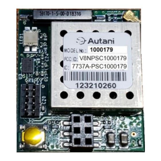
J1 (Off-Module Antenna Connector)
Type
Description
I/O
U.FL Off-Module Antenna Connector
J2 (10-pin Program/Debug Header)
Type
Description
Input
+3.3VDC power supply to module
Output
Program/Debug JTAG Data-Out
Input
Program/Debug JTAG Reset
Input
Program/Debug JTAG Data-In
GND
Power supply ground reference
Input
Program/Debug JTAG Clock
Input
Program/Debug JTAG Mode Select
Input
Program/Debug Processor Reset
Output
Program/Debug Packet Trace Interface Enable
Program/Debug Packet Trace Interface Data
J3 (6-pin Receptacle) – Seral Communication
Type
Description
GND
Power supply ground reference
Input
+3.3VDC power supply to module
Output
UART interface transmit
Input
UART interface receive
I/O
General purpose input/output
Input
Module wake-up interrupt signal
CONFIDENTIAL AND PROPRIETARY
9 of 14
7. Connector Pin
Assignments