Autonics BF4R-E Руководство по эксплуатации - Страница 3
Просмотреть онлайн или скачать pdf Руководство по эксплуатации для Аксессуары Autonics BF4R-E. Autonics BF4R-E 8 страниц. Fiber optic amplifier
Также для Autonics BF4R-E: Руководство (11 страниц), Руководство (7 страниц), Руководство (8 страниц)
- 1. Specifications
- 2. Control Output Diagram
- 3. Installations
- 4. Parts Description
- 5. Setting Mode
- 6. Sensitivity Adjustment
- 7. OFF Delay Timer Function
- 8. Stop Transmission Function [BF4R(G)-E]-Operation Test
- 9. External Synchronization Input Function [BF4R(G)-E]
- 10. Self-Diagnosis Function(Common)
- 11. Interference Prevention Function (Common)
BF4 Series
Dimensions
12
16.4
Installations
Mounting amplifier unit
● When mounting the amplifier
① Hook the front part of the amplifier on
DIN rail(or bracket).
② Press the rear part of the amplifier on
DIN rail(or bracket).
● When releasing the amplifier
Push the back of amplifier toward ③ and
lift the hole for fiber toward ④ up then
simply take it out without tools.
Connection of fiber optic cable & amplifier
Parts description
● BF4R / BF4G / BF4RP / BF4GP / BF4R-R / BF4G-R
B-32
● Connect the bracket
62
36.5
Cable:Ø4, 2m
Control output indicator(red)
Stability indicator(green)
Mode selection switch
Timer selection switch
NON:Not useing timer function
OFD:OFF Delay timer
Sensitivity setting button
12
26.9
14
65.3
● In case of using L bracket
● In case of using screw
※ Notice: If setting bolt is tightened with over
① Open the lock lever to "
② Insert the fiber optic cable in the amplifier slowly.
(Depth: approx. 10mm)
③ Close the lock lever to "
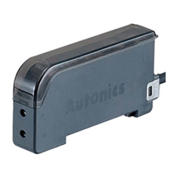
● BF4R-E / BF4G-E
● Bracket
Ø4
35mm DIN rail
useable
Installation of fiber optic cable
L bracket
Fixing nut
Tightening torque:
Max. 2kgf . cm
specified tightening torque, hood of
fiber optic cable may be damaged.
" direction.
" direction.
Control output indicator(red)
Stability indicator(green)
Mode selection switch
External synchronization
selection switch
TRIG:Trigger synchronization
GATE:Gate synchronization
Sensitivity setting button
(unit: mm)
R1.6
16
35
2
14
27
12
1