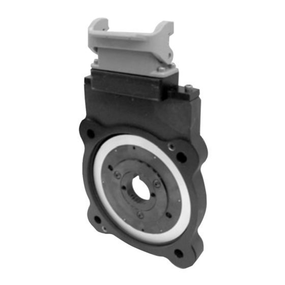
DYNAPAR NorthStar WIND 56 Руководство по эксплуатации - Страница 8
Просмотреть онлайн или скачать pdf Руководство по эксплуатации для Измерительные приборы DYNAPAR NorthStar WIND 56. DYNAPAR NorthStar WIND 56 12 страниц. Magnetoresistive encoder for pitch control unit applications

2.2 To install the encoder frame, perform the following steps:
NOTES:
1. The encoder and the wheel are a matched set and are not interchangeable. The serial numbers should be
double checked to ensure proper assembly and performance. The serial number on the encoder is found
on the encapsulation (example: 102). The serial number on the wheel is found on the front of the wheel
(example: 102W).
2. The ENDURANCE 56 wheel consists of two parts:
A. The hub (secured to the shaft).
B. The pulse wheel (secured to the hub).
1) Install Hub: Position the hub so that the large flange faces the motor. Slide the hub on the motor shaft
until it makes contact with the machined step. See Figure3. If there is not a machined step, see Figure 3a to
illustrate how to use the installation spacer to align the hub. The hub is now properly aligned. Apply Loctite
222 to the two 10-32 UNC set screws. Making sure the hub is firmly seated against the step or installation
spacer, use a 3/32 inch hex wrench to tighten the screws to a nominal 25 in-lbs.
2) Install Encoder Housing: Orient the encoder frame so the 4.5 inch I.D. surface will fit over the 4.5 inch C
flange (encapsulated side toward the motor). Do not bolt down.
PULSE WHEEL
Figure 3: Typical Motor Mounting
3) Install the Pulse Wheel: While holding the encoder frame, position the pulse wheel so the label This Side
Out is visible. Slide it unto the shaft until it makes contact with the hub. Rotate the pulse wheel on the hub so
the three mounting holes are aligned. It may be helpful to use two 1/4-20 UNC screws lightly threaded into
the pulse wheel to help position the pulse wheel. Apply Loctite 222 to the three 8-32 UNC button head
screws. Use a 3/32 inch hex wrench to tighten the screws into the pulse wheel to a nominal 20 in-lbs. Re-
move the two 1/4-20 UNC screws from the pulse wheel.
4. Install Brake Plate and Encoder Housing Hardware: Place the brake plate onto the motor shaft so the
four counter bore holes align with the holes in the encoder frame. Insert the four 3/8-16 UNC screws through
the brake plate and encoder frame and into the motor frame. Use a 5/16 inch hex wrench to tighten a nominal
25 in-lbs.
+1.800.873.8731
©DYNAPAR
Page 8
NorthStar WIND 56 Instruction Manual
HUB
ENCODER
702820-0001 Rev. C
INSTALLATION
SPACER
HUB
Figure 3a: Hub alignment with
installation spacer
June 2012
