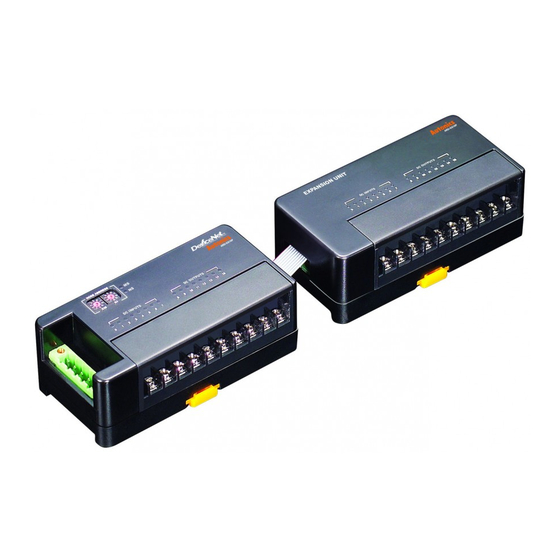
Autonics ARD-DI16NE Руководство - Страница 7
Просмотреть онлайн или скачать pdf Руководство для Системы ввода/вывода Autonics ARD-DI16NE. Autonics ARD-DI16NE 8 страниц. Devicenet digital remote i/o
Также для Autonics ARD-DI16NE: Руководство (8 страниц)

ARD-D Series
Dimensions
Sensor connector type
● Mounting on DIN rail
31
26
Status LED
Item
Module status(MS)
LED
Network status(NS)
LED
Setup And Installation
Node address setup
● Two rotary switches are used for setting node address.
X10 switch represents the 10's multiplier and X10 switch represents the 1's multiplier.
Node address is settable from 0 to 63.
● Node address is changed when re-supplying the power to the unit.
After changing node address, must re-supply the power.
Mounting on panel
① Pull Rail Locks(standard terminal block type: 3EA, sensor connector type: 2EA)
on the rear part of a unit, there are fixing screw hole.
② Place the unit on a panel to be mounted.
③ Make holes on fixing screw positions.
④ Fasten the screw to fix the unit tightly.
Tightening torque should be below 0.5N·m.
C-148
● Mounting with screws
12
2-Ø4.5
LED status
Description
Red
Green
●
Unrecoverable error
●
Recoverable error & communication error of expansion unit
●
Normal operation
●
●
Power is not supplied
●
Normal standby
●
Network On-Line
●
Duplicate, MAC ID / Bus-Off
●
Time Out
●
●
Network Off-Line
● Connector
※ Tightening torque: 1.8 to 2.5N·m
※ Same dimensions are applied to
35.3
85.4
9.8
both basic and expansion unit.
(
: ON,
: Flash,
: OFF)
(Ex)
X10
X1
(unit: mm)
