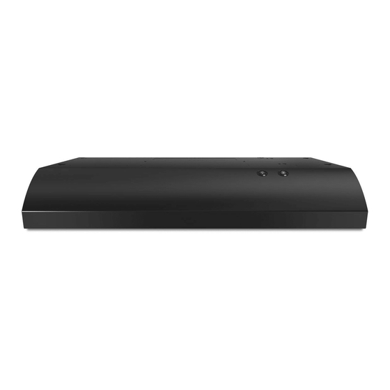
Whirlpool UXT4236AD Инструкции по установке и руководство по эксплуатации и уходу - Страница 8
Просмотреть онлайн или скачать pdf Инструкции по установке и руководство по эксплуатации и уходу для Вентиляционная вытяжка Whirlpool UXT4236AD. Whirlpool UXT4236AD 28 страниц. 30" (76.2 cm) and 36" (91.4 cm) range hood
Также для Whirlpool UXT4236AD: Руководство по установке (34 страниц), Инструкции по установке и руководство по эксплуатации и уходу (28 страниц)

7. Drill Electrical Opening
Using a 1¹⁄₄" (3 cm) drill bit, drill the hole in the dot marked
previously at the electrical strain relief.
OPTIONAL: Using a ¹⁄₈" (3 mm) drill bit, drill pilot holes for the
dots marked previously at each mounting tab at an approximate
45° angle in an upward direction.
8. Prepare Range Hood Vents and
Mounting Tabs
C
B
A
Install Strain Relief
Install a UL Listed/CSA Approved ¹⁄₂" (13 mm) strain relief (A).
Mounting Tabs
Start a #8-18 x ⁵⁄₈" (4.2 x 16 mm) truss-head screw into the
mounting tab (F) on each side of the range hood as shown in
the inset. Insert the screws approximately 2 turns into the
mounting tab holes.
Non-vent (Recirculating) Installations
Using a #2 Phillips screwdriver remove the 2 screws and
remove the top, front rectangular vent cover (E). Go to Step
12.
3¹⁄₄" x 10" (8.3 x 25.4 cm) Rectangular Vent Installations
For top vent installations, remove the top, rectangular vent
knockout (C).
For wall vent installations, remove the rear rectangular vent
knockout (B).
7" (17.8 cm) Round Vent Installations
Remove both top knockouts (C and D).
8
F
x2
E
D
OR
9. Attach Vent Damper or Transition
3¹⁄₄" x 10" (8.3 x 25.4 cm) Rectangular Vent Damper
Using (2) short Phillips head screws, install the 3¹⁄₄" x 10"
(8.3 x 25.4 cm) rectangular damper over the top or rear vent
knockout removed in Step 8.
NOTE: If the wall cap used has a damper and it interferes
with the rectangular damper, remove the rectangular damper
flap.
7" (17.8 cm) Round Vent Mounting Plate
B
Using (2) short Phillips head screws, install the 7" (17.8 cm)
round vent mounting plate over the vent knockouts removed
in Step 8. Position the wide flange (C) to the front.
NOTE: An optional 7" (17.8 cm) round damper (A), Part
Number W10355451, and a 7" (17.8 cm) round vent mounting
plate (B), Part Number W10388168, are available as
accessories. For information on ordering, see the "Assistance
or Service" section.
If installing the optional round damper, position it over the
round vent mounting plate.
A
C
