AluTeam BR 248-2 Инструкция по сборке Руководство - Страница 6
Просмотреть онлайн или скачать pdf Инструкция по сборке Руководство для Грузовики AluTeam BR 248-2. AluTeam BR 248-2 12 страниц. Box body kits

1
Series 248-2 Assembly Instructions
Floor support
Adapter
MA 350147
Molex pin
Adapter
MA 350148
2
Molex socket
Dated 11/2021
3.2 Installing the frame crossmembers
•
Now position the bottom frame crossmember supplied between the
frame pillars.
•
Fix the crossmember from the outside of the pillars with 4 screws
M 12 x 45 mm each. Do not tighten the screws yet!
•
You have now stably connected all the walls to each other. Check
and if necessary, correct the angularity and diagonal dimensions
of the parts assembled until now.
3.3 Attaching the roof
•
If a kit includes doors, before attaching the roof, undo the lashing
straps of the doors. However, the doors must continue to be secured
against turning.
•
If a kit includes a top tailgate, use assembly screws (included in the
material for the top gate) to fix it onto the roof flange using the
holes provided in the hinge.
•
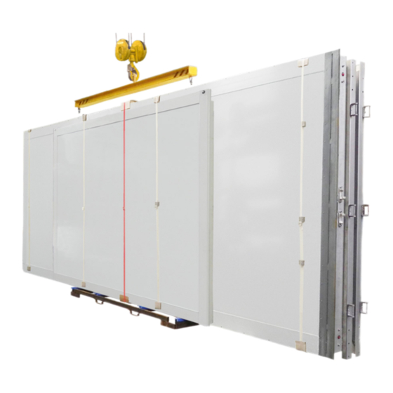
Use a crane and lifting gear or vacuum lifting beam to remove the
roof from the transport unit. Position the roof horizontally and hook
the single-stud fittings into the roof assembly rails (if you are work-
ing without a vacuum lifting beam). The fittings must be tight! 4 or
more fittings are required, depending on the kit length.
•
Push the top frame gusset plates, with the pointed tip facing down-
wards, sideways into the frame crossmember. If applicable, insert
the side lights into the crossmember.
•
Screw the gusset plates with 2 screws MD 100227 and plain washers
10.5 mm each by hand so that they are slightly tightened.
•
Lift the roof with the single-stud fittings or the vacuum lifting
beam. Centre the roof, starting from the front, on the top rail of
the front wall (bulkhead). The roof caps grip over the corner pillars.
Align the roof with the wall sections.
Danger:
Never step under raised loads! Wear a helmet.
horizontal roof at the assembly's centre of gravity,
never lift it with an inclined angle
3.4 Wiring the kit and fastening the roof
•
Lower the roof slowly. If necessary, use a painter's putty knife as
an assembly aid. Centre the downward pointing frame gusset plates
in the pillars. Fix them on each side with three vertically positioned
hexagon head cap screws MD100227 and plain washer 10.5 mm -
finger-tight!
Attention:
The screws must not tilt, the cables and connectors
must not be crushed!
•
Install the cable connections of the 248-2 kits as follows:
•
To wire the side lights, fit together the
1.
plug-in connection on the right and push
2.
the cables into the right-hand frame pillar.
Previous instructions become invalid.
Lift the
(see
1.3)!
6 / 12
