Alvin 2201 Инструкции по сборке - Страница 2
Просмотреть онлайн или скачать pdf Инструкции по сборке для Внутренняя отделка Alvin 2201. Alvin 2201 4 страницы. Parallel straightedge
4. Mark screw positions for front and rear
connectors and pre-drill pilot holes about ¼" deep
" drill bit. TIP: Wrap masking
using a
⁄
1
16
tape ¼" from drill tip to set drilling depth.
Use care not to drill through tabletop.
5. Fasten front connectors to front edge of board
as shown in Figure 2 using ¾" screws. Fasten
screws half way. Do not fully tighten.
6. Assemble right rear connector as shown in Figure 3
and fasten to board. Select screw length based upon
board thickness.* Fasten screws securely.
*For board thicknesses of 5/8" or less:
If your board is
5
⁄
" thick or less please use the
8
⁄
" screws in place of the ¾" screws as shown in
5
8
Figures 3 and 4. Do not use ¾" screws included
with hardware kit since they might break through
bottom of board.
7. Assemble left rear connector as shown in
Figure 4 and fasten to board. Fasten screws
securely. Pulleys are designed to be tight fitting
and do not spin freely.
8. Place straightedge in center of drawing board
parallel to front edge as shown in Figure 5.
9. Loop upper wires around pulleys in rear wire
connectors making sure that spring is centered.
10. Thread lower left and lower right wires through
front wire connectors. Wire should pass
between connector and board as shown in
Figure 6.
11. With spring still centered at top, pull slack out
of wire passing through lower left connector
and wrap wire around mounting screw. Fasten
screw securely.
12. Pull slack out of wire passing through lower right
connector until spring at top is stretched to about
2½" in length. Wrap wire around mounting screw
and fasten screw securely. Use care to set spring
tension as directed for best performance.
13. Excess wire can be trimmed off leaving
several inches for future adjustment.
Figure 2
Front connector
¾ "
Screw
Figure 4
¾ "
Screws*
¾ "
Screws*
Left Rear
Connector
Figure 5
Center spring on board
Stretch spring to 2½" in length
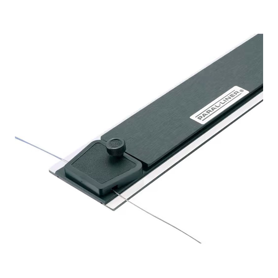
Brake Knob
Figure 6
Figure 3
¾ "
Screw
Rear Brake
Knob
¾ "
Screw*
½ "
Brake
Stud Screw
* Use the
5
⁄
" screws in place
8
of the ¾"screws for boards
⁄
" thick or less.
5
8
Brake Knob
for proper tension
Brake Knob
Straightedge
⁄
"
3
8
Washer
Pulley
Post
Right Rear
Connector
Rear