ASL INTERCOM WS-400 Kullanıcı Kılavuzu - Sayfa 4
İnterkom sistemi ASL INTERCOM WS-400 için çevrimiçi göz atın veya pdf Kullanıcı Kılavuzu indirin. ASL INTERCOM WS-400 9 sayfaları. Base station for wireless intercom with four tx/rx modules
5.0
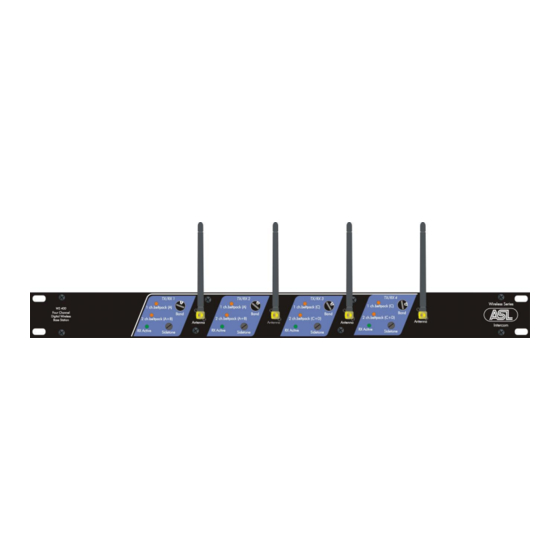
FRONT PANEL CONTROLS
1
RX active LED
This LED will be lit when the RX/TX Unit receives data
from an active beltpack (Talk and/or
beltpack is only listening it will not be lit.
2
Audio Routing LED indicators
Indicate the audio routing for either a WS-19 single
channel beltpack or a WS-29 dual channel beltpack.
See section 7.0 "Automatic Audio Routing"
3
SIDE TONE trimmer
This trimmer adjusts the level of your own voice as you
hear it in the headset which is connected to your
wireless beltpack. The operating area is between fully
clockwise and minimum level.
6.0
REAR PANEL CONTROLS & CONNECTORS
On the WS-400 rear panel are the controls & connectors of channel A, B, C and D.
The drawing shows the controls & connectors of only channel A and B.
6
INTERFACE MODE switch
This switch determines the mode of the audio interface
and the function of the XLR connectors #9 and #10.
See section 8 "The Interface to Wired Intercom"
7
OUTPUT LEVEL trimmer
This trimmer adjusts the output level of the audio signal
that comes from the beltpack.
8
INPUT LEVEL trimmer
This trimmer adjusts the input level of the audio signal
that is sent to the wireless beltpack.
9
OUTPUT connector
This male XLR-3 connector is for connecting either
party line wired intercom or 4-wire intercom. See section
8 "The Interface to Wired Intercom".
Call).
When a
User Manual WS-400 / February 2011 © ASL Intercom BV .
Adjusting the side tone does not affect the level of your
voice as it is heard by other stations. For adjustment
procedure, see section 10 "Setting up Connections"
4
Channel Select switch
With this switch the TX/RX channel is selected on which
the base station communicates with the beltpack. There
is a choice out of 8 TX/RX channels. The selected
TX/RX channel must match the TX/RX channel which is
selected on the beltpack. See also section 9.1
"Frequencies".
5
ANTENNA connector
On this connector the supplied antenna‟s are to be
connected.
10
INPUT connector
This female XLR-3 connector is for connecting either
party line wired intercom or 4-wire intercom. See section
8 "The Interface to Wired Intercom".
11
LINK connector
This Sub-D connector contains all signals that need to
be interchanged when two or more base stations are to
be used in the same space. Only use the special WS
link cable supplied by ASL.
12
MAINS switch
With this switch the WS-200 can be switched on or off.
13
MAINS connector with fuse holder
This mains input accepts 90 – 240 V AC, 50 – 60 Hz.
The fuse in the fuse holder needs to be 1.25 Amp of the
slow blow type. The bottom part contains a spare fuse.
PAGE 4