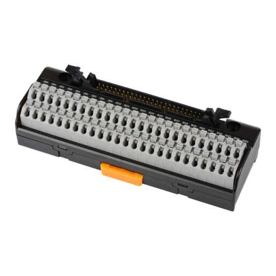
Autonics AFL-H50 Hızlı Başlangıç Kılavuzu - Sayfa 2
Ölçüm Cihazları Autonics AFL-H50 için çevrimiçi göz atın veya pdf Hızlı Başlangıç Kılavuzu indirin. Autonics AFL-H50 3 sayfaları. Interface teminal block

-|Transparent Guide|-
Ordering Information
This is only for reference.
For selecting the specific model, follow the Autonics web site.
AFL
-
H
❶ The number of connector pin
20: 20-pin
26: 26-pin
40: 40-pin
50: 50-pin
❷ Connector
No-mark: HIF3BA, XG4A-2031, XG4A-2631
B: HIF3BB
Sold Separately
• I/O cable
Specifications
Model
AFL-H20
The number of
20
connector pin
The number of
20
terminal
Terminal type
Screwless
Terminal pitch
5.0 mm
20-pin Omron
Connector for
(XG4A-2031)
controller side
Material
Case, Base: PC
Approval
ᜢ ᜨ
Unit weight
≈ 48.5 g
(packaged)
(≈ 86.2 g)
Model
AFL-H20-LN, AFL-H20-LP
The number of
20
connector pin
The number of
16
01)
terminal
Terminal type
Screwless
Terminal pitch
5.0 mm
Connector for
20-pin Omron (XG4A-2031)
controller side
Input logic
NPN / PNP model
Indicator
Power indicator: red, operation indicator: blue
Material
Case, Base: PC
Approval
ᜢ ᜨ
Unit weight
≈ 48.6 g
(packaged)
(≈ 86.3 g)
01) Four terminals among twenty terminals are used for LED power.
02) Eight terminals among fourty terminals are used for LED power or N.C (Not Connectred) terminals.
Basic model: ≤ 125 VDCᜡ, 125 VACᜠ 50/60 Hz
Rated voltage
01)
Indicator equipped model: ≤ 24 VDCᜡ ± 10%
Rated current
≤ 1 A
Insulation
≥ 1,000 MΩ (500 VDCᜡ megger)
resistance
Dielectric
2,700 VACᜠ 50/60 Hz for 1 minute
strength
0.75 mm amplitude at frequency of 10 to 55 Hz (for 1 minute) in each X, Y, Z
Vibration
direction for 2 hours
Vibration
0.75 mm amplitude at frequency of 10 to 55 Hz (for 1 minute) in each X, Y, Z
(malfunction)
direction for 10 minutes
Shock
150 m/s
2
Shock
100 m/s
2
(malfunction)
Ambient
-15 to 55 ℃, storage: -25 to 65 ℃
(a non freezing or condensation environment)
temperature
Ambient
35 to 85 %RH, storage: 35 to 85 %RH
humidity
(a non freezing or condensation environment)
Protection
IP20 (IEC standard)
structure
01) When connecting loads to output part, connect loads of same power type. Connecting loads of different power
type may cause safety issues.
Applicable wire
Ø 0.3 to 1.2 mm
- solid
01)
Applicable wire
AWG 22-16 (0.30 to 1.25 mm²)
- stranded
01) 02)
Wire ferrule
connection
≥ 30 N
tensile strength
Stripped length 8 to 10 mm
01) Use the cable of copper conductor in 60 ℃ temperature class.
02) When using the stranded wire, use End Sleeve (wire ferrule).
Wire Ferrule Specifications
• Unit: mm, Use the UL approved wire ferrule.
❶
❷
-
❸
❹
❸ Indicator
No-mark: no LED
L: LED equipped
❹ Input logic
No-mark: None
N: NPN
P: PNP
AFL-H26
AFL-H40
AFL-H50
26
40
50
26
40
50
Screwless
Screwless
Screwless
5.0 mm
5.0 mm
5.0 mm
26-pin Omron
40-pin Hirose
50-pin Hirose
(XG4A-2631)
(HIF3BA-40PA-
(HIF3BA-50PA-
54DSA)
2.54DSA)
≈ 60 g
≈ 89 g
≈ 110 g
(≈ 89 g)
(≈ 156 g)
(≈ 177 g)
AFL-H40-LN, AFL-H40-LP
40
32
02)
Screwless
5.0 mm
40-pin Hirose (HIF3BA-40PA-2.54DSA)
≈ 91 g
(≈ 158 g)
(≈ 15 G) in each X, Y, Z direction for 3 times
(≈ 10 G) in each X, Y, Z direction for 3 times
10 to 12
≤ 4.1
≤ 2.0
Dimensions
• Unit: mm, For the detailed dimensions of the product, follow the Autonics web site.
A
B
20-pin
AFL-H50B
26-pin
50
40-pin
50-pin
50
Screwless
5.0 mm
Installation
50-pin Hirose
(HIF3BB-50PA-
■ DIN RAIL
2.54DSA)
• Mounting
1. Pull the Rail lock on the rear of the product to the direction ①.
≈ 110 g
2. Hang DIN rail hook on the rear of the product onto DIN rail.
(≈ 177 g)
3. Push the product to the direction ②, and push the Rail lock to the direction ③ to fix
onto the DIN rail.
• Removing
1. Insert a tool such as screwdriver into the hole of Rail lock.
2. Push the toll to the direction ① and pull the Rail lock.
3. Lift bottom of the product to the direction ② and remove the product from DIN rail.
■ Panel
Product with the mounting hole can be installed on panel with screw.
It is recommended to use M4×25 mm of spring washer screws.
If you use flat washer, its diameter should be Ø 8 mm.
Tighten the screw with the tightening torque of 0.7 to 1.0 N·m.
Wiring
• Connecting
Insert the wire ferrule into the terminal hole.
• Removing
1. Put the (-) screwdriver at the groove on the clamp lever
and press it.
2. Pull the cable to disassemble.
C
2-M4
A
B
C
D
57.5
53
2-Ø4.2
53
72.5
64
2-Ø4.2
64
106.5
89
2-Ø4.5
89
131.5
102
2-Ø4.5
102
DIN rail hook
DIN rail
Rail lock
①
③
①
②
Rail lock
Mounting hole
D
35 mm DIN RAIL
②
3
