Agrowtek VX8i Kullanım Kılavuzu - Sayfa 3
Kontrolör Agrowtek VX8i için çevrimiçi göz atın veya pdf Kullanım Kılavuzu indirin. Agrowtek VX8i 15 sayfaları. Digital irrigation valve controller

Component Locations
Remove the cover by looseneing the two bottom screws and removing the top two screws.
Tilt the cover back to clear the light pipes and then remove the cover.
The PCB has several connection and con guration options as described:
1
2
1. I/O Screw Terminal Block
Make connections to analog sensor inputs and transistor outputs.
2. Input Jumper Select Block
Set input channels to current mode (0-20mA) instead of voltage (VX12i only)
3. Power Input Terminals
Optional input power terminals for hard wire applications.
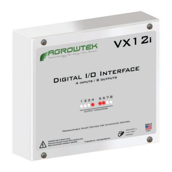
4. LED Light Pipes
Indicators for each of the eight (8) outputs; red when on. Pipes protrude through front panel openings.
3
3
© Agrowtek Inc. | www.agrowtek.com | Technology to Help You Grow™
GND
GND
GND
GND
4
