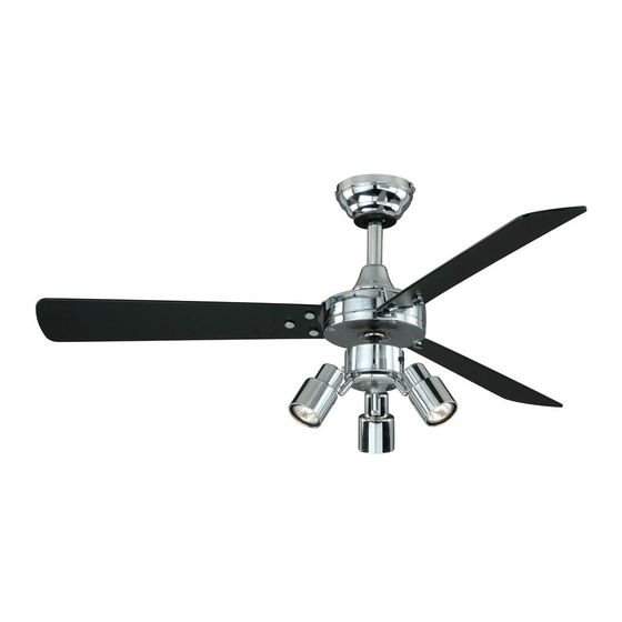
aireRyder F0020 Manuel - Sayfa 7
Fan aireRyder F0020 için çevrimiçi göz atın veya pdf Manuel indirin. aireRyder F0020 9 sayfaları.

Switch Box
Wire Connector
Suction Cap
GU10 LED Bulb Max.10W
GU10 LED Bulb
3X6W (included)
Reverse
Slide Switch
Forward
Fan Light Pull
Chain
Fig.17-a
Install two pull chains and drops onto the pull chains located in the switch box and light kit.
The pull chain controls the fan speed as follows:
1 pull – High, 2 pull – Medium, 3 pull – Low, and 4 pull – Off.
To turn the light kit "ON" or "OFF", pull the chain that is attached to the light kit.
Caution: If you install a remote control or a wall control for this fan, pull the pull chains to "high speed" of the
fan motor and "on" of the fan light.
Fig.18
Make wire connection:
-- connect the blue wire from the switch
box to blue wire from the fan light with
wire connector.
-- connect the white wire from the switch
box to white wire from the fan light with
wire connector.
Fan Light
Carefully put the wires into the switch box.
Fig.14
Install bulbs (Included).
a. Attach the suction cap to the top surface of the halogen bulb lens.
b. Insert and twist the bulb (GU10 BASE MR16C BULB ONLY) into the socket
by using the suction cap.
c. Remove the cupule from the halogen bulb lens by pulling the knob of the suction
cap.
d. Repeat with other bulbs.
Note: Do not discard the suction cap, it will be needed when replacing the
bulb.
Note: Adjust the spotlight head to a desired position by using the swivel.
Fig.16
Caution: Turn off the power and allow the fixture to cool down completely
before relamping the lamp.
Switch Box
Fan Speed Pull
Chain
Install pull
chains and
drops
Turn ON the electric power at the main fuse
or circuit breaker box.
The slide switch on the switch box sets the direction of fan rotation.
Select the
desired
direction of fan rotation. Push the slide switch
down for " Forward" and up for "Reverse".
Note: Wait for fan to stop before reversing the direction of blade
rotation.
Reverse
Slide Switch
Forward
Switch Box
Screw
Secure the fan light onto the switch box
by using the switch box screws.
Fig.17-b
F
A
N
180725
Fig.15
C
O
