Align 3GX V2.1 Kurulum - Sayfa 2
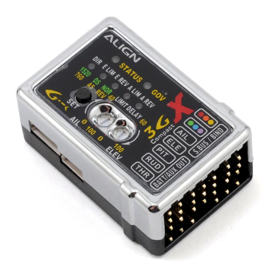
Kontrol Ünitesi Align 3GX V2.1 için çevrimiçi göz atın veya pdf Kurulum indirin. Align 3GX V2.1 4 sayfaları. Easy setup table

Swashplate Settings
5. Swashplate cyclic pitch setting: with the main
blades parallel to helicopter body, throttle stick
positioned where main pitch is 0 degrees, move
aileron stick all the way to the right, adjust the AIL
mixing ratio within radio's SWASH menu so the
main blade pitch is the factory recommended
value ±8 degrees.
6. The ELE mixing ratio in SWASH menu can be set
to the same value as AIL.
Setting 2
LED
LED2 Lit
Setting
Elevator Travel Limit Setting
Setup Method
While keeping swashplate level and main pitch at
zero degrees, press the SET button to register the
neutral point and enter E.LIM
setup mode. The E.LIM LED will lit up after DIR
turns off.
2.The throttle stick position where main pitch is 0
degree must be maintained through this setup
process.
3. With all channels stationary, move the
transmitter elevator stick forward, and then back
to center position. This completes the swashplate
mixing type recognization process. The control
unit will determine the CCPM mixing ratio or
traditional mechanicalmixing maximum elevator
endpoints.
5. Maintain Throttle stick position where main
pitch is 0 degree through this setup process.
Setting 3
LED
LED3 lit
Setting
Elevator gyro setting
Setup Method
1. Press the SET button to enter E.REV setup
mode. The E.REV LED will lit up after E.LIM turns
off. This setup mode sets the elevator gyro
direction
2. Tilt the helicopter forward as shown in diagram,
and check if swashplate is tilting correctly toward
the back.
3. If the swashplate is tilting at the wrong
direction, move the transmitter elevator stick until
STATUS LED changes color, and re‐check the
swashplate tilting direction.
3GX V2.1 Easy Setup Table (English).xlsx
Align 3GX V2.1 ‐ Setup Summary
Speed Governor Settings
7. When governor is functioning, engine rotational speed is
controlled by the percentage set by user. The rotation speed of
main blade is converted according to the engine ratio of original
helicopter.
8. Using the chart on the right to obtain engine rotation speed and
head speed under corresponding governor channel percentage.
D du Rand ‐ July 2012
Rudder Settings
LED2 Lit
Digital/Analogue Servo Selection
1. There is a direct correlation between servos' speed to gyro's
performance. Faster servos are able to execute commands
from the gyro at faster and higher precision. Due to the high
performance gyro sensors used in the 3G flybarless system,
premium high speed digital rudder servos are mandatory for
optimal tail performance. Some of the recommended rudder
servos include Align DS650, DS620, DS520, DS420, Futaba
S9257, S9256, S9254, S9253, or other servos with similar
specifications.
2. Setup method:Press and hold the SET button for 2 seconds
to enter the setup mode, then press the SET button to select
DS/AS setup mode, as indicated by the lighting of DS/AS LED.
Using the transmitter's rudder stick, select either digital servo
DS mode (STATUS LED is green),or analog servo AS mode
(STATUS LED is red).
LED3 lit
Rudder Gyro NOR/REV Setting
1. Lift up the helicopter by hand, and turn it to the left (yaw).
Check if the rudder servo is applying correct compensation to
the right. If reversed, set the NOR/REV setting as follow.
2.Setup method:Press and hold the SET button for 2 seconds
to enter the setup mode, then press the SET button to select
NOR/REV setup mode, as indicated by the lighting of NOR/REV
LED.
3. Using the transmitter's rudder stick, select either NOR
(STATUS LED is green), or REV (STATUS LED is red).
Flight Mode Setting
STATUS flashes green twice
Elevator travel limit setting
1. Before entering elevator and aileron limit setting, please switch
the transmitter to throttle hold mode and push the throttle down
to 0 degree position to avoid mechanical interference due to
excess travel range.
2. After entering setting mode, STATUS LED flashes twice
3. After entering setting mode, elevator may deviate as much as 8
degrees plus compensating rate either forward or back. Moving
elevator stick can adjust servo travel limit. For example, if LED
shows 50%, total elevator travel range is 8+0.5*8 = 12 degrees.
4. Generally 70% is suitable for most helicopter frame. If
recommended value is not used, please adjust setting until
maximum is reached without mechanical binding.
STATUS flashes green 3 times
Aileron travel limit setting
1. After entering setting mode, STATUS LED flashes 3 times.
2. After entering setting mode, aileron may deviate as much as 8
degrees plus compensating rate either forward or back. Moving
aileron stick can adjust servo travel limit. For example, if LED
shows 50%, total elevator travel range is 8+0.5*8 = 12 degrees.
3. Generally 70% is suitable for most helicopter frame. If
recommended value is not used, please adjust setting until
maximum is reached without mechanical binding.
2 of 4
