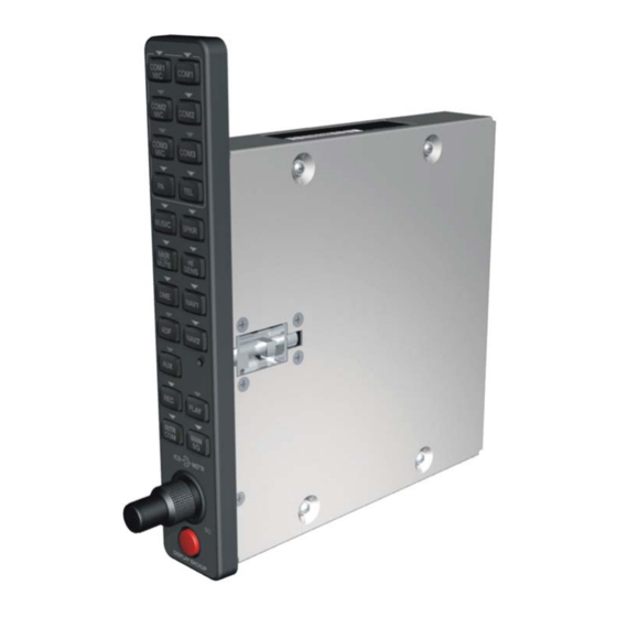
Garmin 011-01257-00 Kurulum Kılavuzu - Sayfa 22
Aviyonik Ekran Garmin 011-01257-00 için çevrimiçi göz atın veya pdf Kurulum Kılavuzu indirin. Garmin 011-01257-00 47 sayfaları.

2.7
Installation Approval Considerations for Pressurized Aircraft
Antenna and cable installations on pressurized cabin aircraft require FAA approved installation design
and engineering substantiation data whenever such installations incorporate alteration (penetration) of the
cabin pressure vessel by connector holes and/or mounting arrangements.
For needed engineering support pertaining to the design and approval of such pressurized aircraft antenna
installations, it is recommended that the installer proceed according to any of the following listed
alternatives:
1. Obtain approved antenna installation design data from the aircraft manufacturer.
2. Obtain an FAA approved Supplemental Type Certificate (STC) pertaining to and valid for the
subject antenna installation.
3. Contact the FAA Aircraft Certification Office in the appropriate Region and request identification
of FAA Designated Engineering Representatives (DERs) who are authorized to prepare and
approve the required antenna installation engineering data.
4. Obtain FAA Advisory Circular AC-183C and select (and contact) a DER from the roster of
individuals identified thereunder.
5. Contact an aviation industry organization such as the Aircraft Electronics Association and request
their assistance.
2.8
Electrical Noise
Because the audio panel is a point in the aircraft where signals from many pieces of equipment are
brought together, take care to minimize effects from coupled interference and ground loops.
Coupled interference can sneak into audio system interconnecting cables when they are routed near large
AC electric fields, AC voltage sources and pulse equipment (strobes, spark plugs, magnetos, EL displays,
CRTs, etc). Interference can also couple into audio system interconnecting cables by magnetic induction
when they are routed near large AC current-carrying conductors or switched DC equipment (heaters,
solenoids, fans, autopilot servos, etc).
Ground loops are created when there is more than one path in which return currents flow or when signal
returns share the same path as large currents from other equipment. These large currents create
differences in ground potential between the various equipment operating in the aircraft. These differences
in potential can produce an additive effect on audio panel input signals.
The audio panel may "see" the desired input signal plus an unwanted component injected by ground
differentials, a common cause of alternator-related noise. This is the main reason why all audio jacks
should be isolated from ground. Terminating audio shields just at one end eliminates another potential
ground loop injection point.
Single-point grounding cannot be overstressed for the various avionics producing and processing audio
signals. Single-point, in this context, means that the various pieces of equipment share a single common
ground connection back to the airframe. Good aircraft electrical/charging system ground bonding is also
important.
The wiring diagrams and accompanying notes in this manual should be followed closely to minimize
noise effects.
Page 2-6
Revision C
GMA 1347D Installation Manual
190-00303-21
