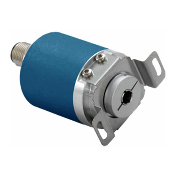
Avtron HS6M Talimatlar Kılavuzu - Sayfa 2
Medya Dönüştürücü Avtron HS6M için çevrimiçi göz atın veya pdf Talimatlar Kılavuzu indirin. Avtron HS6M 16 sayfaları. Hollow shaft 6-15mm

Equipment needed for installation
Supplied:
HS6M Encoder
Anti-Rotation Tether
Optional:
Shaft Sizing Insert
Not Supplied:
Wrenches
Dial Indicator Gauge
Caliper Gauge
The hollow shaft HS6M design eliminates the potential for coupling
failures from misalignment, however, excessive housing movement
(wobble) may cause undesirable vibrations and bearing damage.
The higher the RPM, the more severe the vibration will be from
housing movement. In a typical installation a housing movement of
0.004" [0.1mm] TIR or less (as measured at the outside diameter of
the main encoder body) will not have an adverse effect.
1)
Disconnect power from equipment and encoder cable.
2)
Use caliper gauge to verify motor shaft is proper diameter and
within allowable tolerances: +0.000", -0.0005"
[+0.00, -0.013mm].
3)
Clean machine shaft of any dirt and remove any burrs.
4)
Use dial indicator gauge to verify the motor shaft: Total
Indicated Runout (TIR) <0.002" [0.05mm].
5)
Install the anti-rotation bracket tether to the face of the encoder
included with the tether.
6)
Loosen clamping collar screws.
7)
Test Fitting: carefully slide the encoder onto the shaft to verify
fit. Ensure a minimum of 1/16" [1mm] between encoder and
mounting surface. DO NOT FORCE. Encoder should slide on
easily. If the encoder does not fit easily, remove it, verify shaft
size, and check for burrs and shaft damage.
8)
Slide the HS6M onto the shaft. Ensure minimum insertion
requirements shown on drawing page are met.
9)
Tighten screws on clamping collar evenly until snug, then
tighten each screw as follows:
For bore sizes up to 1" [25mm] 38 in-lb [4.3 Nm]
For bore sizes >1" [25mm] 66 in-lb [7.5 Nm]
DO NOT USE A STANDARD RIGHT ANGLE WRENCH. Use only a
T-handle hex wrench or torque wrench with hex bit.
10) Secure free end(s) of the anti-rotation bracket to frame using
bolt or T-bolt provided. The bracket should be parallel to the
encoder face, 90 degrees to the shaft to avoid encoder bearing
damage. Use additional washers as needed to ensure the
tether is parallel to the encoder face.
12) Turn shaft by hand and verify the shaft turns freely and does
not produce excessive runout/wobble of the encoder (<0.005"
TIR [0.13mm], Total Indicated Runout.) Ensure the tether arm is
secure and the encoder body cannot rotate.
13) Connect cable as shown in wiring diagram.
14) Apply power to the encoder.
15) Rotate the shaft by hand, or using jog mode of the speed
controller and verify proper direction and position output.
ENVIRONMENTAL CONSIDERATIONS
Follow these steps to reduce potential problems:
1)
Always mount connection points, conduit couplings, junction
boxes, etc., lower than actual encoder.
2)
For washdown areas, shroud or otherwise cover the encoder to
prevent direct water spray. Do not attach the shroud directly to
the encoder.
REPAIRS
REMOVAL INSTRUCTIONS:
1.
Unbolt tether arm from mounting point(s) on motor.
2.
Loosen clamping collar screw(s).
3.
Slide the encoder off the motor.
REPLACING PARTS
The HS6M has two items that are user-replacable in the field in
case of damage, or to change the encoder electrical or mechanical
interface:
1.
Shaft sizing insert: Simply slide the insert out of the HS6M and
replace it with the new bore size insert. Insert should remove
and install with modest force-do not pound the insert into the
HS6M.
2.
Tether system: To replace the tether system, remove the
retaining screw(s), then replace with the new tether.
CAUTION
Do not attempt to remove, service, or adjust any of the
internal components of the HS6M.
INSTALLATION
Refer to the back page of these instructions for outline and mounting
dimensions.
Equipment needed for installation
Supplied:
Encoder
Optional:
(none)
Not Supplied:
Open Wrenches, Hex Wrenches, Dial Indicator Gauge
Caliper Gauge, Mounting Screws
WIRING INSTRUCTIONS
CAUTION
Remove power before wiring.
Interconnecting cables specified in the wire selection chart are
based on typical applications. Refer to the system drawing for
specific cable requirements where applicable.
Physical properties of cable such as abrasion, temperature, tensile
strength, solvents, etc., are dictated by the specific application and
communications bus. Do not use unshielded cable. Ground one end
(only) of the shield to earth ground.
Do not run encoder wiring parallel to power cable wiring for
extended distances, and do not wrap encoder cable around power
cables.
TROUBLESHOOTING:
If the controller indicates a loss of encoder fault, check the encoder
power supply at the encoder. If power is present at the encoder,
check polarity. If the wiring appears correct and in good shape,
test the wiring by replacing the HS6M. If the controller still shows
encoder loss/fault, then the wiring is faulty and should be repaired or
replaced.
An oscilloscope can also be used to verify output of the HS6M
encoder at the encoder connector itself and at the drive/ controller
cabinet. Depending on the communication method, signals will vary
but the oscilliscope should show the output signals varying. Keep in
mind that SSI and Profibus DP are master-slave systems and require
the controller to signal the encoder to transmit position.
SSI TROUBLESHOOTING
For SSI, monitor the clock input line to ensure the controller is
triggering the encoder to send position. The clock should obey the
signal requirements shown in the SSI signal section, and should
appear as a rapid set of transitions on the clock line. The encoder
data transmit lines should change state as data is clocked out. Note
that the varying binary patterns representating position can produce
pulses of varying width--this is normal.
PROFIBUS-DP TROUBLESHOOTING
HS6M
2
