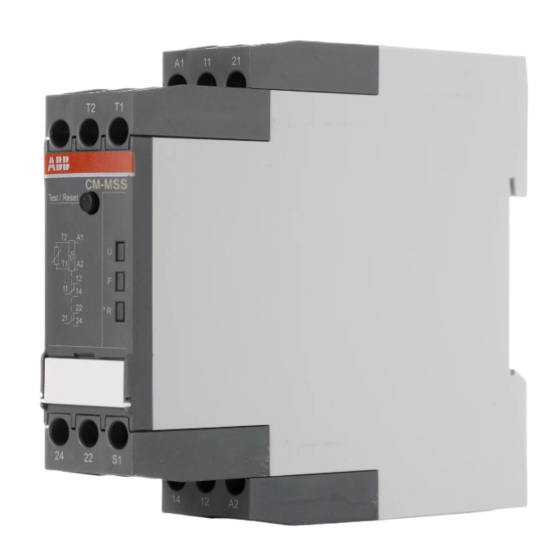
ABB CM-MSS.33 Güvenlik Talimatı - Sayfa 10
Röleler ABB CM-MSS.33 için çevrimiçi göz atın veya pdf Güvenlik Talimatı indirin. ABB CM-MSS.33 20 sayfaları. Thermistor motor protection relays

Monitoring functions
The thermistor motor protection relay CM-MSS monitors the
winding temperature and thus protects the motor from
overheating, overload and insufficient cooling.
For this the motor has to be equipped with PTC resistor
sensors type A. If the motor heats up excessively (sensor
resistance > 2.83 kΩ, CM-MSS.12/13/22/23: > 2,7 kΩ), the output
relays de-energize. A reset is only possible after cooling down
of the motor (sensor resistance < 1.1 kΩ, CM-MSS.12/13/22/23:
< 1,2 kΩ).
Short-circuit detection
(CM-MSS.21/31/32/33/41/51)
If a short circuit is detected between the two lines of a sensor
circuit, the output relays de-energize.
Dynamic interrupted wire detection
(CM-MSS.11/21/31/32/33/41/51)
During the operation the device is permanently monitoring the
measuring circuit. If the resistance in the measuring circuit is
changing, the device recognizes on the basis of the velocity of
change if there is a interrupted wire. Then the output relays de-
energize.
Test function
(CM-MSS.31/32/33/41/51)
is only possible when there is no fault.
By pressing the front-face combined Test / Reset button a
system test routine is executed.
CM-MSS.41/51: If the function „Remote Test / Reset" (DIP
switch 4) is activated, the system test routine is also possible
via control input S1-T2 (CM-MSS.41) or S1-1T2/2T2 (CM-MSS.51).
After starting the test routine the output relays de-energize.
They remain de-energized until the Test / Reset button is
pressed again or control input S1-T2 (CM-MSS.31/32/33/41) or
S1-1T2/2T2 (CM-MSS.51) is closed (remote reset).
Reset (CM-MSS.11/12/13/21)
Once the fault has been rectified and the measured value has
dropped below the release threshold, an automatic reset is
executed.
Reset (CM-MSS.22/23/32/33)
After rectification of a fault, the device has to be reset. This
reset can be made manually by the Reset button, automatically
by jumpering S1-T2 or externally by a remote reset between
S1-T2.
Fault storage and reset (CM-MSS.31)
The fault storage is designed as non-volatile (remanent). After
switch-off and return of the control supply voltage the device
returns to the state it was prior to the switch-off.
If prior to the interruption of control supply voltage there was
no fault, the device restarts automatically after re-applying
control supply voltage.
If there was a fault prior to the interruption, reset can be made
manually by the Test / Reset button, automatically by
jumpering S1-T2 or externally by a remote reset between S1-T2.
Fault storage f and reset (CM-MSS.41/51)
The fault storage is designed as non-volatile (remanent). This
means that after switch-off and return of the control supply
voltage the device returns to the state it was prior to the
switch-off.
If prior to the interruption of control supply voltage there was
no fault, the device restarts automatically after re-applying
control supply voltage.
If there was a fault prior to the interruption, reset can be made
manually by the Test / Reset button or externally by a remote
reset between S1-T2 (CM-MSS.41) or S1-1T2/2T2 (CM-MSS.51).
With deactivated fault storage reset can be made manually by
the Test / Reset button, externally by a remote reset between
S1-T2 (CM-MSS.41) or S1-1T2/2T2 (CM-MSS.51) or automatically
by jumpering S1-T2 (CM-MSS.41) or S1-1T2/2T2 (CM-MSS.51).
Single and accumulative evaluation (CM-MSS.51)
Single evaluation
i
If a fault occurs in the measuring circuit 1, output relay 1 (11-
12/14) de-energizes. If a fault occurs in the measuring circuit 2,
output relay 2 (21-22/24) de-energizes.
Accumulative evaluation
j
In case of a fault in one of the two measuring circuits, both
output relays de-energize synchronously.
All operating states are signaled by the front-face LEDs.
See table „LEDs, status information and fault messages".
Page 10/20
